
A modified speedcore system.
The composite plate shear wall-concrete filled (C-PSW/CF) system, also referred to as the SpeedCore system, is a modular construction system where wall modules are composed of two steel faceplates, concrete infill, and tie bars connecting the face plates. While the system is somewhat similar to the system previously introduced by Corus (now TATA steel) in the early-mid 2000s and marketed in the United Kingdom (UK) as CoreFast, the SpeedCore system has significant differences from CoreFast. The key feature of the CoreFast system is that the elements are shop-fabricated using a patented friction stir welding process to connect the tie bars to the inside of the face plates, whereas SpeedCore is a nonproprietary system (Huber et al., 2021). Although CoreFast was not widely used outside of the UK, the SpeedCore system is emerging as an alternative to conventional reinforced concrete (RC) shear walls in the US. This is due to both constructability advantages for steel buildings, research undertaken by the nuclear industry, and, more recently, the research led by Purdue University and the University at Buffalo. The SpeedCore system is now addressed in the American Institute of Steel Construction’s AISC 360-22 Specification for Structural Steel Buildings, AISC 341-22 Seismic Provisions for Structural Steel Buildings.” and AISC Design Guide 38 “SpeedCore Systems for Steel Structures.” This article presents alternative approaches to connecting Speedcore modules to simplify construction.
Studies for the Rainier Square project in Seattle, WA, performed by contractors, indicated that the use of SpeedCore reduced construction time. As a possible substitute for reinforced concrete shear walls, SpeedCore walls resist gravity, lateral wind, and seismic loads. An advantage of SpeedCore is in commercial high-rise buildings where steel is generally the primary structural material, and either steel bracing or reinforced concrete shear walls around the building core are used for building stability. SpeedCore provides the lateral strength and stiffness associated with reinforced concrete shear walls. Although this system might utilize more steel material than conventional reinforced-concrete wall systems, it has the benefit of eliminating conventional formwork and steel reinforcement bars. The construction schedule is also improved since all steel construction moves ahead in unison, and only the concrete infill operation follows a few days behind. This sequence is similar to the concrete-on-composite deck construction method. With SpeedCore, there is no traditional shear wall construction to sequence before or after steel framing installation. Such steel-centric construction methods could simplify construction coordination, scheduling, and logistics. The fabrication, construction methods, and tolerances are generally the same for SpeedCore walls and adjacent structural steel floor framing.
The SpeedCore system has been used in two projects: the Rainier Square Building in Seattle, WA, and the 200 Park Ave Building in San Jose, CA. For these projects, a ductile lateral force-resisting system was required for seismic design even though seismic forces did not necessarily govern the Rainier Square building member sizes. As reported for these buildings (Morgen et al., 2018), the SpeedCore system had a competitive advantage over other systems that are commonly used in high-seismic areas. For the 200 Park Ave building, recent improvements and refinements of the system were implemented through additional research at Purdue University and the University at Buffalo. To further increase the advantage of the SpeedCore system, especially for areas of lower ductility demand, this article proposes an alternative, proprietary method of detailing the SpeedCore system that reduces the amount of field welding and simplifies the connections at the interfaces between individual wall modules (Rahimian et al., 2022, U.S. Patent 11,352,786 B2). This alternative detailing approach is based on AISC and the American Concrete Institute (ACI) standards, as applicable, with experimental verification currently planned. The proposed alternative approach is not part of the AISC Design Guide 38, “SpeedCore Systems for Steel Structures.”
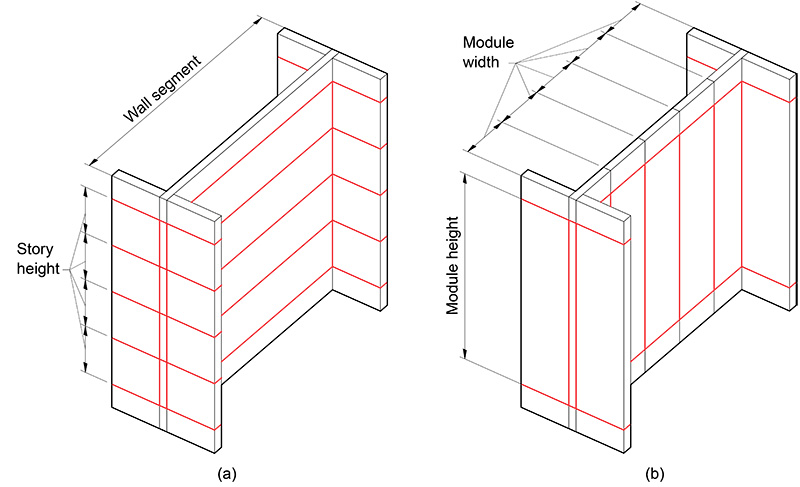
Module Sizing
Maximizing offsite fabrication and reducing the piece count of field-connected elements is key to achieving economy for any prefabricated system, including SpeedCore. Therefore, using the largest prefabricated wall module size that can be efficiently produced and shipped is preferable. Currently, the widest plate commonly rolled in the United States is limited to a 10-foot width, while the maximum shippable length is typically 50 feet; the shipping length and width can be increased subject to special permitting by local authorities. Domestic facilities with the capability of rolling wider plates are coming online. However, only a limited number of domestic suppliers have this capability. Whereas previous designs of the SpeedCore system used horizontally oriented modules with horizontal joints approximately at every floor (Fig 1a), the proposed alternative orients the modules long-side-vertical, extending upward for a height of two to three floors with a standard module width of approximately 10 feet, or wider when possible. The proposed arrangement (see Figure 1b) also allows increased flexibility to place SpeedCore wall modules around elevator shafts, stairs, and other building core elements. The primary intent of this modular arrangement is fewer horizontal joints, which are structurally more demanding than vertical joints. Furthermore, it offers steel contractors the option of fabricating narrower modules, giving them more control over fabrication, transportation, and erection in projects where wide modules may present challenges.
Joints
Recent seismic applications of SpeedCore featured field joints between steel plates using field welding to join adjacent wall modules. If the yield strength of the plates is fully utilized or if high levels of inelastic deformation capacity are needed, field-welded joints, including complete joint penetration (CJP) welds, are typically needed. However, even in a high-ductility system, full continuity of the faceplates should be only required in certain sections, and not all, of the structure. Using performance-based design principles, areas with large inelastic strains (e.g., plastic hinge zones) can be identified where faceplate continuity is needed. Outside such areas, simpler joining methods can be utilized. In traditional SpeedCore construction, the horizontal joints between modules can be highly stressed due to axial, bending, and shearing stresses. In contrast, vertical joints between adjacent wall submodules are subjected to mostly in-plane vertical shear forces that result from in-plane flexure of wall segments and are very different from horizontal joints. Detailing strategies that eliminate field welding should lower the overall cost of the system.
Steel module plate thickness may be governed by considerations other than strength, and therefore plate material might not be fully utilized in strength calculations of module joints. Less than full utilization of the faceplate may be a result of plate thickness being governed by crosstie spacing and practical aspects of plate thickness selection. The spacing of the ties is related to plate thickness based on two criteria: 1) the pre-composite stiffness of the wall module for constructability, and 2) plate buckling between ties in the composites state for design loads. The pre-composite stiffness of the empty modules is important for transportation, shipping, and handling. Plate local buckling between ties may occur under a full load if the tie spacing is too large and the plate slenderness ratio is too high. The AISC Design Guide seeks to eliminate plate elastic local buckling. Plate thicknesses of less than 3/8 inches are often impractical since thinner plates may be difficult to handle in fabrication and result in modules that are too flexible for assembly, installation, and concrete placement. Faceplate thickness will typically range from 3/8 inches to 5/8 inches. Greater thickness may be used in zones of high seismic demand. It is generally more economical to have fewer ties, even if the plate thickness is increased slightly to meet stiffness and slenderness limits, since installing them is labor intensive. Consequently, in many cases, the development of the full tensile strength of a plate in the joint is not required unless the wall element is in a demand-critical location where plastic hinging is expected. Although field welding using CJP joints is a viable way to connect all wall modules, alternative ways to achieve the needed joint performance in regions of low demand should be considered. (In principle, identical to detailing transverse reinforcement in special reinforced concrete shear walls.)
Horizontal Joints
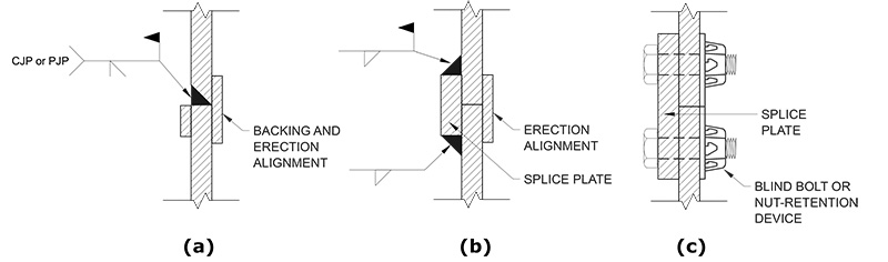
Depending on the utilization of the steel plate in strength calculations, the full strength of a faceplate at a horizontal joint may not be required. Some of the potential alternatives for the horizontal joint details are shown in Figure 2.
Figures 2b and 2c offer alternatives to CJP and PJP welds, namely, fillet welds and bolted splices. Such connections, possibly to be used where strength demands are low, require less onerous inspection. Option (a) represents the current standard practice for welded joints, and option (b) has been studied by Ramesh (2013, 2014). Research and testing are underway at the University at Buffalo on the use of bolted splices such as option (c) and other bolted alternates (Huber, 2022). These alternatives also provide greater tolerance for field adjustment since the gap between the faceplates can be larger than the maximum root opening for a PJP or CJP weld. Since access to the back side of the faceplate is not possible after the module is placed, a bolted option would most likely require a proprietary product: either a blind bolt or a nut retention system. Bolted connections are often preferred by steel contractors due to speed and easier quality control but require additional allowances for splice thickness.
Vertical Joints
Vertical joints between wall modules must have adequate strength to ensure that the adjacent modules are connected to act as a single structural element. These vertical joints will likely not need to develop the full strength of the faceplate outside plastic hinge zones. Eliminating field welding in vertical joints offers opportunities for speedier construction and significant cost reduction. These alternatives are presented by Rahimian et al. (2022, “Constructing Buildings with Modular Wall Structure,” U.S. Patent 11,352,786 B2).
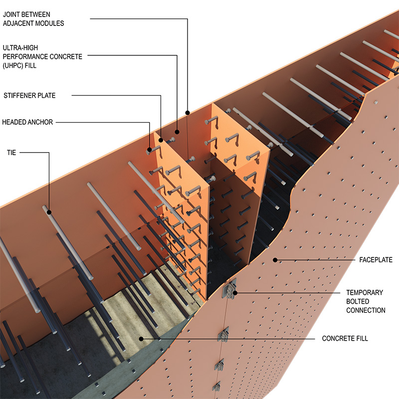
The shear transfer across the vertical interface between adjacent wall modules may be achieved through concrete and headed stud anchors attached to stiffener plates welded to the faceplates, as shown in Figure 3. Similar force transfer mechanisms in composite structural elements have been used in multiple projects (Tuchman,1988,Viest,1997) and are covered by the AISC 360 specification; Chapter I. Figures 3, 4, and 5 show the proposed approaches for shear transfer through concrete. As shown in Figure 3, a fiber-reinforced concrete or ultrahigh-performance concrete (UHPC) mix can be deposited into the cavity between the stiffener plates, potentially with no need for additional reinforcement. Normal or high-performance concrete, along with limited steel bar reinforcement, could be used, as shown in Figures 4 and 5. (The workability of UHPC would need to be evaluated depending on the module size and construction details.)
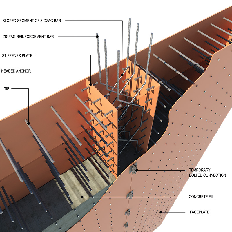
The vertical stiffener plates shown in these figures stiffen the individual wall modules, facilitating shipping and lifting without temporary bracing, and allowing empty 3-story high units to resist wind and construction loads in the pre-composite state. Adjacent modules may be held in place temporarily during erection using bolted clip angles. If these angles cannot be concealed within the wall finish construction, they can be removed after the infill concrete gains the required strength.
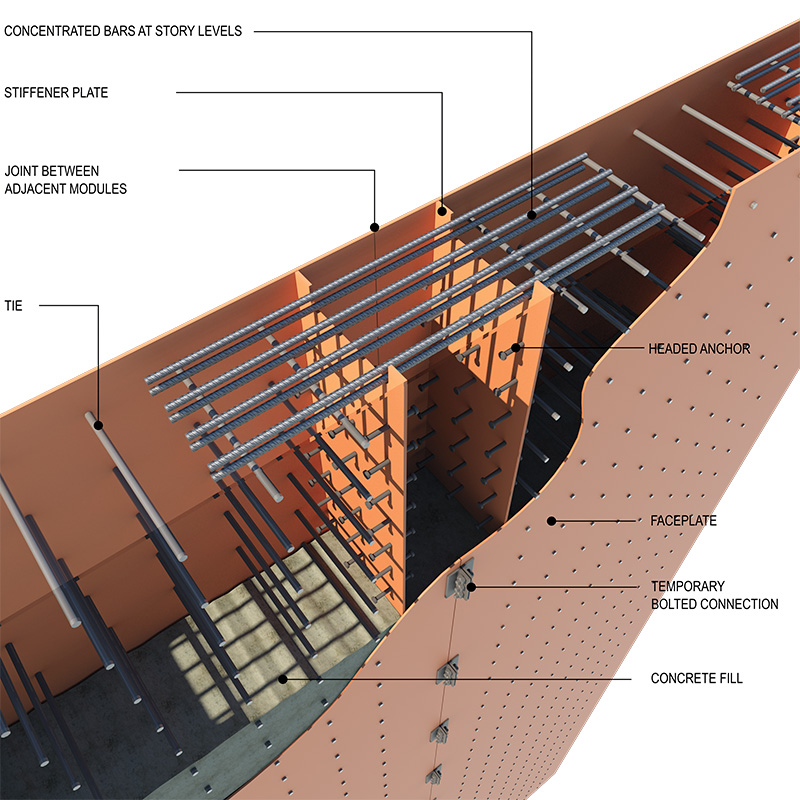
Shear transfer across vertical joints between adjacent wall modules can be achieved using steel bar reinforcement using the shear-friction provisions of Chapter 22 of ACI 318-19. Steel bar reinforcement placement may require a separate trade, so the benefits of reducing field welding versus involving another construction trade must be considered on a case-by-case basis. Kurt et al. and Seo et al. experimentally and analytically investigated the connection of steel-concrete composite walls to reinforced concrete members via noncontact lap splices of reinforcement bars and steel face plates. The same approach could be used for shear transfer in vertical joints. A variation of this approach may be to use stiffener plates with headed stud anchors on each side of the joint, forming a secondary vertical mini-joint cell at the joint between adjacent wall modules with reinforcement bars in the joint area. Shear-friction bars crossing the vertical plane of the joint may be positioned in the mini-joint cell after adjacent modules are held in place by temporary bolting. Shear-friction reinforcement that crosses the vertical plane between adjacent modules does not need to be placed as horizontal bars that are uniformly distributed along the wall module height. Instead, these bars can be arranged in different ways to simplify the placement of that reinforcement during module erection. The reinforcement could be strategically concentrated in zones of easier access (Figure 4). Alternatively, reinforcement can be detailed to intersect the shear friction plane at multiple locations as a series of bent bars. Such bars may be pre-bent and lowered into the cavity between faceplates as a prefabricated reinforcement cage (Figure 5). Furthermore, concentrated horizontal bars may be placed at the top or bottom of the modules (Rahimian et al., 2022), further simplifying the installation of shear-friction reinforcement and speeding the joining of adjacent wall modules.
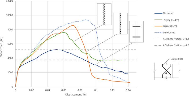
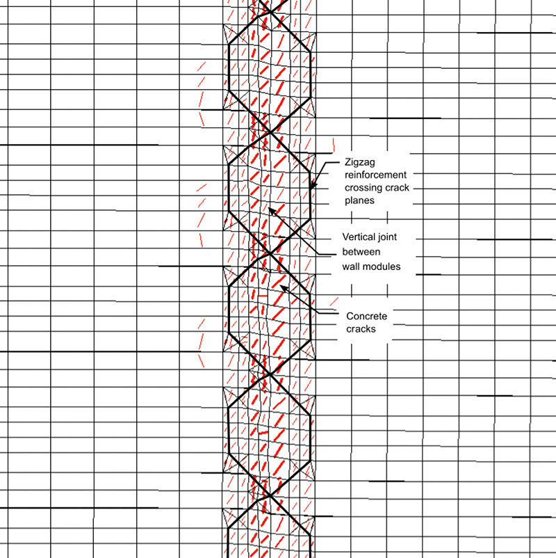
A series of numerical studies were performed for the proposed joint cell under shear loading using the VecTor2 nonlinear finite element software (Wong et al., 2002). The analysis considers steel and concrete material nonlinearity (Vecchio, F.J., Collins, M.P., 1986). This analysis was performed for monotonically increasing loads. The study simulated “pure shear” conditions in the joint for a 24-inch thick wall with 8000 psi concrete fill and ½-inch thick face plates, with a height of 28 feet. (Further analysis under reversed cyclic loading is planned in conjunction with a testing program.) Numerical studies were performed for the proposed zigzag and clustered reinforcement options shown in Figures 4 and 5; uniformly distributed horizontally was used as a benchmark. The reinforcement area was the same for all options. Although the sloped segments of zigzag bars (Fig. 5) may be arranged at any angle, only 0° and 45° were considered here. The clustered and zigzag reinforcement arrangements are much easier to install in sequence with steel module erection than the benchmark uniformly distributed reinforcement. Figure 6 shows the load-deformation behavior under monotonic loading for all four reinforcement configurations. The total area of reinforcement crossing the vertical plane of the joint cell is the same in all four cases. The study indicates that both the angle of reinforcement and the spacing of the bars in the cell affect joint shear strength. To enable a comparison, the figure also shows the ACI 318 shear friction strength using coefficients of friction of 1.0 and 1.4. Figure 6 indicates that the proposed rebar arrangements provide strength similar to that calculated using the ACI 318 shear friction model. Figure 7 shows the VecTor2 crack patterns for the zigzag option at the peak load.
Link Beams
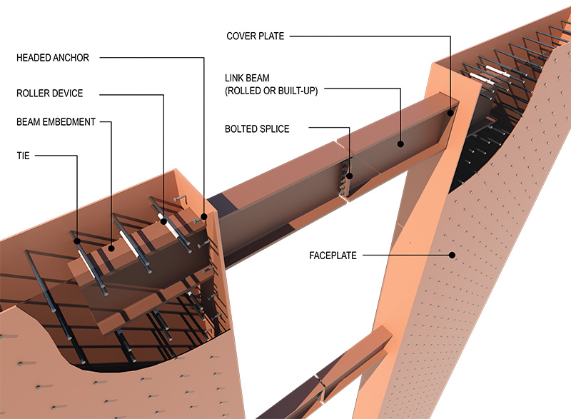
Link beams (also called coupling beams) that connect adjacent wall segments in the areas around door openings in tall buildings are some of the most challenging elements to design and detail. The overall system ductility, fabrication, and erection need to be considered. AISC Design Guide 38 addresses the coupling beam design, recognizing composite concrete-filled and steel-only beams. Bruneau and Varma et al., 2019 studied SpeedCore concrete-filled link-beam box sections and connections between box-section beams and SpeedCore walls. That study considered coupling beam connections using continuous web plates and interrupted wall flange plates, as well as connections using lapped web plates and continuous wall flange plates and face plates from outside. In the first option, wall flange plates are interrupted and welded to the beam flange plate, where the beam flange plates penetrate the wall and are welded to the wall web plates. In the second option, beam flange plates are welded to uninterrupted wall flange plates. According to Bruneau and Varma et al., box-beam welds, used to connect the coupling beam flanges and web plates to the composite wall steel plates, are designated as demand critical and, therefore, they are required to meet the additional requirements in AWS D1.8. Furthermore, concrete placement in such composite link beams requires a mix that can flow in and fill the box section without forming cavities due to air pockets. Special holes in the beam top flange would be needed, and these holes should be accounted for in the box beam design. Although AISC Design Guide 38 discusses steel-only link beams as an alternative for non-seismic applications, steel I-beams embedded (rolled or built-up) in concrete walls are a recognized seismic lateral force-resisting system per AISC 341 (Section H4). I-shape link beams can be incorporated into the proposed SpeedCore system while meeting the intent of AISC 341 provisions. Even though AISC Design Guide 38 describes the concrete fill inside the composite walls as “plain” concrete, the AISC 360 specification and a substantial body of research recognize the ductility of the composite wall elements and the fact that steel plates act as “reinforcement” for the concrete fill in a manner similar to conventional reinforcement in cast-in-place concrete walls. In addition, the AISC Design Guide 38 references the fundamental mechanics-based model (MBM) for the in-plane shear behavior of composite walls. The shear strength provisions in the guide and in the AISC 360-22 specification are based on MBM principles. The mechanics-based model developed by Varma et al. (2014) and Seo et al. (2016) explains how the shear strength of the composite section is mobilized through a compressive stress field in the concrete and a simultaneous tensile stress field in the face plates. This behavior is characteristic of reinforced concrete membrane elements, as studied by Rahimian (2019). It is, therefore, consistent with the AISC 341 specification to utilize the beam embedment provisions for composite shear walls (Section H4) with SpeedCore walls. Openings may be provided in the vertically oriented wall module flange plates to receive the steel link beams. The beams may be preset within the wall module during shipping and slide, into position after the wall modules are erected. If the beam embedment length or the opening width is too large, a bolted splice may be provided at the mid-span of the link beam (see Figure 8).
Conclusions
The SpeedCore wall system is a new development in the construction of steel buildings. It is considered a ductile system and suitable for use in regions of high seismic hazard. The alternative construction proposed in this article is intended to reduce the cost of the SpeedCore system by reorienting the wall modules, reducing the field welding of horizontal joints, and replacing vertical welds with composite connections. The proposed joint solution could be widely used for buildings in regions of low seismic hazard with small inelastic deformation demands and in segments of buildings in regions of high seismic hazard where plastic hinging is not expected. The additional benefit of the proposed joining method is increased tolerance in vertical joints between modules due to the elimination of field welding.
The proposed modified link-beam design based on conventional steel I-shape members could help simplify the coordination, fabrication, and construction of coupling beams.
Increased construction speed through offsite prefabrication of major structural elements has the potential to minimize risks, improve quality and safety, and mitigate disruptions in urban areas. New innovative systems, such as those presented here, are key to making the composite concrete-filled wall system an economical and viable alternative to conventional reinforced concrete shear walls.■
Acknowledgements
The authors would like to thank Professor Andrew Whittaker at the University at Buffalo, and Professor Emeritus Frank Vecchio of the University of Toronto for their comments on the drafts of this manuscript.
References
Zhao, Q., and Astaneh-Asl, A., (2004), “Cyclic Behavior of Traditional and Innovative Composite Shear Walls,” Journal of Structural Engineering, ASCE, Vol. 130, No. 2, pp. 271–284.
Sabelli, R. and Bruneau M., (2006), “Steel Plate Shear Walls,” Design Guide 20, AISC, Chicago, IL.
Ramesh S., Kreger M., Bowman M., (2014), “Design Procedure for Dual-Plate Composite Shear Walls,” Design Report Submitted to Charles Pankow Foundation.
Ramesh S., Kreger M., Bowman M., (2013), “Behavior And Design Of Earthquake-Resistant Dual-Plate Composite Shear Wall Systems” Design Report Submitted to Charles Pankow Foundation.
AISC., (2016a), ANSI/AISC 341-16, Seismic Provisions for Structural Steel Buildings, American Institute of Steel Construction, Chicago, IL.
AISC., (2018), ANSI/AISC N690-18, Specification for Safety-Related Steel Structures for Nuclear Facilities.
Bruneau M., Varma A., Kizilarslan E., Broberg M., Shafaei S., Seo J., (2019). R-Factors for Coupled Composite Plate Shear Walls/Concrete Filled (CC-PSW/CF). Final Report prepared for Charles Pankow Foundation & American Institute of Steel Construction.
Varma, A.H., Zhang, K., Chi, H., Booth, P.N. and Baker, T., (2011a), “In-Plane Shear Behavior of SC Walls: Theory vs. Experiment,” Transactions of the Internal Association for Structural Mechanics in Reactor Technology Conference, SMiRT-21, Div. X Paper 761, New Delhi, India, IASMIRT, North Carolina State University, Raleigh, NC.
Varma, A.H., Malushte, S.R., Sener, K., and Lai, Z., (2011b), “Steel-Plate Composite Walls for Safety-Related Nuclear Facilities: Design for Combined In-Plane and Out-of-Plane Demands.” Transactions of the 21st International Conference on Structural Mechanics in Reactor Technology (SMiRT 21), New Delhi, India, Paper ID 760, IASMiRT, North Carolina State University, Raleigh, NC.
Seo, J., Varma, A.H., Sener, K., and Ayhan, D., (2016), “Steel-Plate Composite (SC) Walls: In-Plane Shear Behavior, Database, and Design.” Journal of Constructional Steel Research, Elsevier Science, Volume 119, pp. 202-215.
Epackachi, S., Whittaker, A. S. and Varma, A.H., (2015), “Experimental behavior of flexure critical steel-plate composite SC shear walls,” Trans., 23rd Int. Conf. on Structural Mechanics in Reactor Technology (SmiRT 23), Manchester, UK, IASMIRT, North Carolina State University, Raleigh, NC.
Morgen, B., Klemencic, R., Varma A., (2018), Core Solution, Modern Steel Construction, February 2018. American Institute of Steel Construction.
Rahimian, A., Udilovich, K., Smilow, J., Haque, M., (2022), “Constructing Buildings with Modular Wall Structure” U.S. Patent 11,352,786 B2.
Kurt, E.G., Seo, J.; Varma, A.H., “SC Wall-to-RC Basemat Over-Strength Connection: Behavior and Design,” Civil Eng (2022), 503–524 Seo, J., Anwar, H.S., and Varma, A.H., (2022), “Steel-Plate Composite (SC) Wall-to-Reinforced Concrete (RC) Wall Mechanical Connection – Part 1,” Engineering Journal, AISC, Vol. 59, No. 1, pp. 31–52.
Anwar, H.S., Seo, J., Varma, A.H. and Nam, (2023), “Steel-Plate Composite Wall to Reinforced Concrete Wall Mechanical Connection – Part 2: In-Plane and Out-Of-Plane Shear Strength,” Engineering Journal, AISC, Vol. 60, No.1, pp. 31–59.
Rahimian, A., (2019), “Biaxial Principal Stress Interaction Diagram for Design of Reinforced Concrete Membrane Elements” ACI Structural Journal – Vol. 116, n. 3.
Varma A.H., Broberg M., Shafaei S., Taghipour A.A., (2023), “AISC Design Guide 38, SpeedCore Systems for Steel Structures.”
AISC., (2023), “ANSI/AISC 360-22 Specification for Structural Steel Buildings,” American Institute of Steel Construction, Chicago, IL.
Varma, A.H., Malushte, S.R., Sener, K.C., and Lai, Z., (2014), “Steel-Plate Composite (SC) Walls for Safety-Related Nuclear Facilities: Design for In-Plane Forces and Out-of-Plane Moments,” Nuclear Engineering and Design, Vol. 269, pp. 240–249.
Tuchman, J., (1988), “Architect’s Vision, Bank’s Visibility.” Engineers News Record: pp. 36–46.
Viest, I. M., (1997), “Composite Construction Design for Buildings.” New York, N.Y: ASCE.
Vecchio, F.J., (1989), “Nonlinear finite element analysis of reinforced concrete membranes,” ACI Structural Journal 86 (1), 26–35.
Vecchio, F.J., (1990), “Reinforced concrete membrane element formulations,” ASCE Journal of Structural Engineering 116 (3), 730–750.
Vecchio, F.J., (2000), Disturbed stress field model for reinforced concrete: formulation. ASCE Journal of Structural Engineering 126 (9), 1070–1077.
Vecchio, F.J., (2001), Disturbed stress field model for reinforced concrete: implementation. ASCE Journal of Structural Engineering 127 (1), 12–20.
Vecchio, F.J., Collins, M.P., (1986), The modified compression field theory for reinforced concrete elements subjected to shear. Journal of the American Concrete Institute 83 (2)
Morgen, B., Klemencic, R., and Varma A.H., (2018), “Core Solution”, Modern Steel Construction, Feb., Vol.58, No. 2
Huber, D., and Varma, A., (2021), “Core Value”, Modern Steel Construction, Vol.61, No. 3, Mar., pp.30-37.ACI (2019), Building Code Requirements for Structural Concrete, ACI 318-19 and ACI 318M-19, American Concrete Institute, Farmington Hills, Mich.
Huber, D.,(2022), “Increasing Speed through Research” Modern Steel Construction, December 22
Wong, P. S., and Vecchio, F. J., “VecTor2 & FormWorks User’s manual,” Publication No. 2002-02, Department od Civil Engineering, University of Toronto, Toronto, ON, Canada, Aug. 2002, 214 pp.