
Simplicity in the face of uncertainty.
To design a building to survive an unspecified threat, as it is done in design against progressive collapse, is outside the realm of conventional structural engineering. Without knowing anything about the event, other than it may occur, the objective of the design must be to produce as redundant a structure as possible and as practical within given economic restraints. This exercise amounts to asking the engineer to design for the unknown. There is no time or money to design a building to withstand everything. Given that level of uncertainty, the old engineering adage that computational effort must be proportional to the quality of results rules out the use of detailed, time-consuming calculations.
In agreement with these ideas, the apparent goal of current Codes addressing progressive collapse and blast resistance is not to ensure complete building survival in the mentioned unknown event but to provide a level of structural redundancy deemed sufficient. Nevertheless, the specific analyses and procedures required by the Codes to meet this goal often involve extensive computational time and effort.
To look at the problem from a different perspective, consider this question:
If a designer is tasked with assessing an existing building for progressive collapse (assuming, for instance, that a column may be lost) or tasked during conceptual design to proportion a structure to withstand a given blast, but is told there is no time available for a full structural analysis, how should they proceed? Spending engineering power on the details of the dynamics of a singular immaculate column removal that will never occur as assumed is a waste of engineering power.
This article shows that the stability of a flooring system after the abrupt removal of one support:
- can be judged using the simplest ideas in statics and the conservation of energy,
- can be addressed with a carefully chosen load or safety factor, and
- can be evaluated without the use of software.
This simpler approach, based on principles of dynamics formulated by J.M. Biggs and the fundamental concepts of Virtual Work and Conservation of Energy, provides quick and reasonable results. These results can help the initial proportioning of structural members that can then be checked by more elaborate means if required by regulations.
By way of a design example, we show that this simpler approach produces results comparable to results produced by detailed analyses that require more time. More demonstrations are given by Smith (2009).
Design time can be spent more productively on critical detailing, which is often the main factor determining structural redundancy and tenacity. Detailing is the key to reduce susceptibility to progressive or disproportionate collapse. More time spent on detailing will likely lead to a better structure than computations about a notional event.
The Basis of The Proposed Procedure
In 1964, Biggs introduced the idea that the main aspects of the dynamic response of a continuous system can be understood using a single degree of freedom system chosen so that the kinetic and potential energies in both systems are equal to each other. He arrived at this equivalent system by assigning to it:
- a fraction (0.5 to 0.75) of the mass of the continuous system,
- strength equal to the total strength of the continuous system for static conditions, and
- an applied force equal to the total force acting on the continuous system (which can vary with time).
The equivalent system, so tuned, produces displacements equal to the maximum (reference) displacement in the continuous system.
It follows that, ignoring strain-rate effects, the response of a floor system to the abrupt removal of a support can be understood in terms of the static strength or resistance of the system missing the removed support (𝑅y) and the total weight acting on it 𝑊. Ignoring the effects of damping, the work done by that weight through the peak floor displacement ∆ is 𝑊×∆. That work must be equal to the area under the resistance-displacement curve representing the static response of the system (if strain-rate effects on strength are ignored):
𝑊× ∆ =𝑅y×(∆-∆y/2)
Here ∆y is yield displacement. From this, it follows

or

where 𝑪D𝑅 = 𝑅y/𝑊 is the ratio of static capacity and demand (in terms of total forces acting on a flooring system in the area affected by the support removal), and µ is ductility demand (the ratio of peak floor displacement to yield displacement associated with resistance 𝑅y).
For the unlikely case that CDR>2, estimated ductility is smaller than 1. In that case, the equation of conservation of energy becomes

or

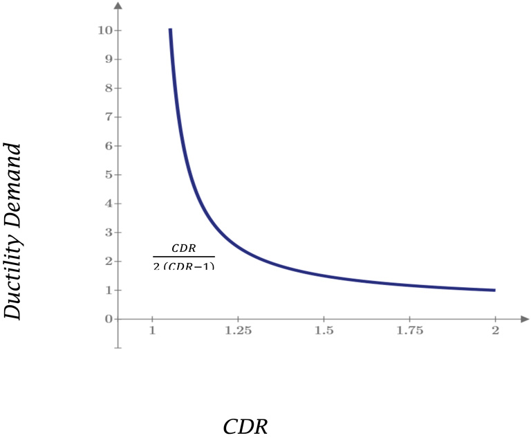
Figure 1 shows a plot of ductility demand v. capacity demand ratio CDR.
Figure 1 suggests that a capacity-demand ratio (or safety factor) of 1.5 results in a small ductility demand of 1.5. A defensible capacity-demand ratio of 1.2 yields a modest ductility demand of 3. Strain-rate effects and strain hardening are bound to increase resistance, and the detailing required to achieve the mentioned ductility values (1.5 to 3) is unlikely to be taxing. This simplified method produces results comparable with those obtained from detailed and time-consuming nonlinear dynamic analyses (Smith, 2009). The engineering solution is simple: almost any acceptable safety factor suffices. The critical decisions affecting the survival of a structure subject to an attack that can render one of its columns useless should not depend on the type of material used in construction. Conservation of energy applies to steel, timber, concrete, masonry, and FRP plastics without discrimination. The critical decisions have to do with the following:
- whether to consider the removal of more than one column at a time (as observed in Oklahoma City, The Pentagon, and WTC), and
- whether to consider damage to the flooring system itself.
Given these rather obvious sources of uncertainties, spending time analyzing instead of detailing seems futile. Instead, simple static analysis and a reasonable factor of safety (exceeding 1.2 to 1.5) should suffice and yield time for careful consideration of details (welds, splices, anchorage, confinement).
The Current Building Code
The U.S. Department of Defense’s UFC 4-023-03, Design of Buildings to Resist Progressive Collapse, offers three approaches for design: ALP – Alternative Load Paths, ELR – Enhanced Local Resistance, and the Tie Method. ELR and the Tie Method mostly relate to critical detailing. Therefore the focus becomes ALP and, in particular, the use of equivalent static analysis to determine initial member proportions.
In the UFC approach, as in conventional force-based design, capacity is required to exceed demand. Capacity refers to estimates for static conditions modified with factors, some of which increase and decrease it:
an m factor (>1) related to the ductility of the structure,
a strength-reduction factor (<1) – as used in conventional design for static forces – that presumably has to do with uncertainties in strength estimation and material properties as well as consequences of failure, and
an overstrength factor (>1), reportedly related to the idea that actual material strengths tend to be larger than nominal strengths.
No explicit connection is made to the plausible effects of loading rates. The idea to increase the capacity in apparently direct proportion to ductility capacity (through factor m) is not explained in better terms other than by saying that it is done to imitate the methods in ASCE-41, Seismic Rehabilitation of Existing Buildings (which has to do with earthquakes instead of impulsive loads).
Demand is modified in two ways (in the same direction this time):
- By using load factors (>1 at least for dead loads) to admit that loads may be larger than expected
- By using a load increase factor (or LIF) that, on average, and according to results from numerical simulations done to select the values recommended in the guidelines (McKay et al., 2012), approaches LIF=m+1 (depending, reportedly, on the properties of the materials in the structure). Note that the guidelines recommend more conservative values.
The main apparent justification for using the LIF seems to be that it was chosen to match dynamic analyses done in SAP2000 (McKay et al., 2012).
Lumping all strength-reduction, strength-increase, and load factors into a single ratio of capacity to demand, the current approach in UFC translates into:
Increased Capacity ≥ Increased Factored Demand:

or, at the limit,

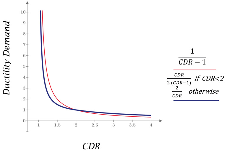
If one assumes m to be a measure of ductility demand µ, then this expression can be compared with the expression obtained before from conservation of energy (Figure 2):
The two curves in Figure 2 are remarkably similar. But why should they not be so? After all, well-written code for numerical simulation ought to produce results consistent with basic physics. Rather, the question is: why can’t the engineer rely on simple physics instead of numerical results?
Both curves tend to infinity at CDR=1. That stands to reason. Both curves produce a ductility demand of 1.0 for a capacity-demand ratio of 2. That is consistent with the proverbial example in which a linear spring supporting a mass deforms twice as much if the mass is let go suddenly instead of slowly. And both curves suggest again that the problem of the dynamics of a ductile floor responding to abrupt support removal can be reduced to choosing a safety factor and decent detailing.
Design Example
The following procedure illustrates how this approach can be used in designing a structure subject to the UFC progressive collapse requirements. It includes four steps:
- Design for gravity + wind/lateral loads
- Perform analyses to estimate static capacity (yield-line analysis should suffice)
- If calculated CDR > 1.2, continue to Step 4.
- If calculated CDR < 1.2, follow Step 3
- Add reinforcing needed to reach the desired ductility
- Revise structural system to provide higher capacity
- Increase member sizes and/or revise detailing
- Perform Code required analyses (as a check)
The following example illustrates that simple physics and consideration of detailing can be used to identify quickly where structures lack redundancy. Nevertheless, the example shows that a detailed analysis would still provide similar results.
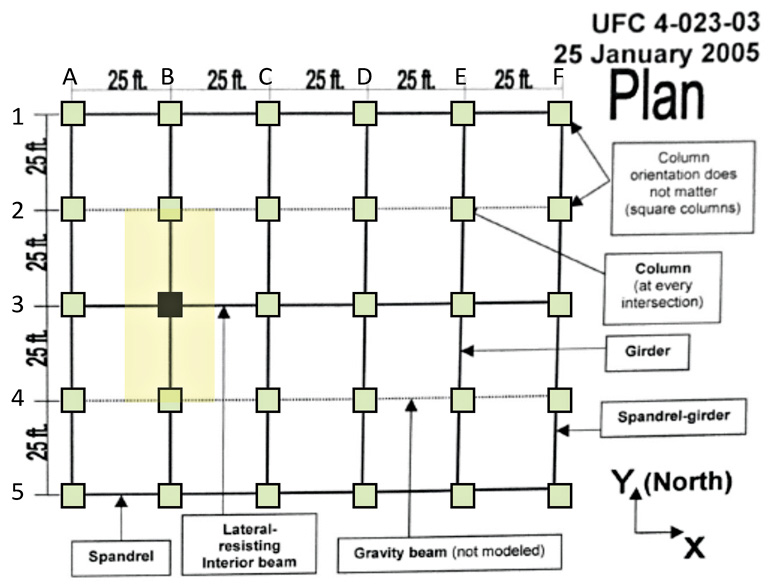
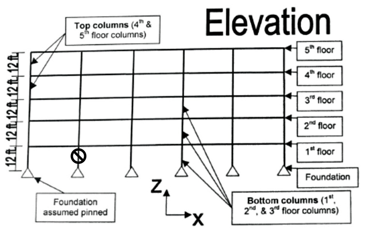
Example 1 – UFC Model
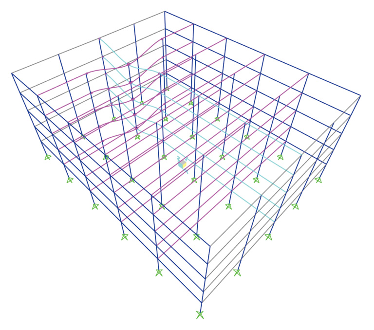
Consider the five-story reinforced concrete building described in UFC (2005) and illustrated in Figures 3a and 3b. Column B3 (marked in dark shading) is assumed to be removed in the ground story.
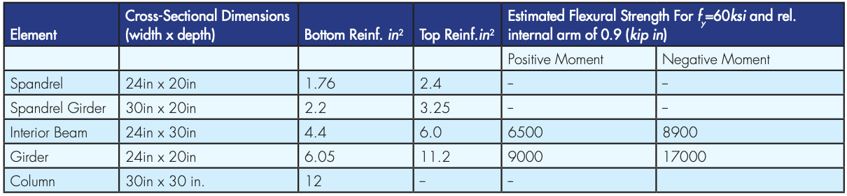
The reinforcement schedule is given in Table 1. Effective depths are taken as total depths minus 2.5 inches.
Static Demand
In this example, it shall be assumed that girders resist the gravity floor loads as uniformly distributed forces corresponding to a uniform tributary width of 25 feet.
Specified loads are 50 psf live load, 90 psf dead load, and self-weight. The simplified analysis presented here focuses on the 25-foot- wide floor area shaded in Figure 3 on both sides of girder B, between axes 2 and 4. For this area, uniformly distributed values of live and dead load are 1.25 kip/ft and 2.25 kip/ft. Girder self-weight is 0.73 kip/ft. The total factored load is wu=4.2 kip/ft using load factors of 0.5 for live and 1.2 for dead loads.
Static Capacity
Table 1 lists flexural strengths estimated for a) internal arm lengths approximated as 0.9x effective depth, and b) reinforcement yield stress fy=60ksi. In the absence of column B3, static resistance is estimated using the principle of virtual work for a flexural mechanism with plastic hinges in beams and girders at nodes A3, B2, B3, B4, and C3. Virtual rotations are taken as 1/25ft at A3, B2, B4, and C3 and 2/25ft at B3. Total internal work associated with a unit vertical displacement at B3 is, therefore:
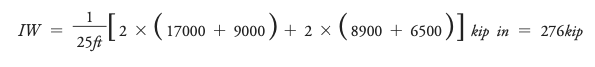
External work is taken simply as the total force acting on girder B2-B4 times average virtual displacement (½) consistent with the assumed mechanism and loading:

Equating EW and IW leads to wy=11 kip/ft=2.6 wu. The ratio of capacity to demand CDR=wy/wu is 2.6>2, indicating the floor system would remain linear. A linear analysis of the structure suggests the deflection associated with the yield force is 1.4 inches, indicating a vertical stiffness of K=7.8 kip/ft/in.
Dynamic Response
The maximum deflection for a sudden application of the load would be twice the static deflection: 2 wu/K =1.1in. A dynamic analysis in SAP2000, including slow application of the loads followed by the sudden removal of column B3, produces a peak displacement of 1.3in (smaller than the yield deflection).
Variations in Reinforcement
A reduction in the longitudinal reinforcement resisting tension in beams and girders to a uniform 4 in2 results in an estimated moment strength of 5900 kip in, instead of the values in Table 1. The associated yield load becomes wy=6.3 kip/ft=1.5 wu. For a ratio of yield capacity to static demand CDR=1.5, the expected dynamic ductility demand becomes

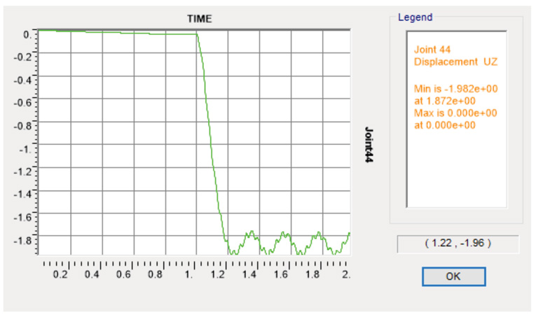
The associated peak displacement is 2.1 in. A nonlinear dynamic analysis in SAP2000 produces a peak deflection of 2 in. The deflected shape and the history of peak displacement (at B3) obtained in that analysis are illustrated in Figures 4a and 4b.
In this example, the results from a simple analysis are compatible with results obtained with elaborate analysis. A close examination of the expression µ=CDR/(2×(CDR-1)), as illustrated in Figure 2, will show that for values of CDR<1.25, small changes in CDR result in large changes in ductility demand. The sensitivity of this relationship may produce deviations among results obtained from different forms of analysis.
Additional Considerations
In line with detailing requirements in the ELR and Tie Method in UFC and outside the comparative example outlined above, a key takeaway for the design engineer performing analysis for progressive collapse is the importance of continuity of reinforcement. Independent of Code-required analysis or the simpler approach presented above, the designer can go a long way towards producing a structure that can perform better under an unspecified threat:
By considering the following for reinforced concrete structures:
- Maximize the continuity of reinforcement
- Provide continuous reinforcement and check lap splices
- Check the shear and punching shear of the frame and slab elements
- Check shop drawings against the design intent of structural drawings.
- Or consider the following for structural steel frames:
- Consider using prequalified Special Moment Frame (SMF) connections.
- Optimize column spacing to maximize floor framing efficiency.
- Provide similar or same beam depths framing into columns w/stiffeners for ease of connection detailing.
- Orient floor framing to provide adequate LTB bracing of primary Alternate Path structural elements.
- Check shop drawings against the design intent of structural drawings.
Conclusion
To design a floor to survive abrupt column removal choose a ratio of static nominal capacity to static demand exceeding 1.2 to 1.5, and spend more time on detailing instead of the numerical analysis of the dynamics of an event that may never occur.
References
Biggs, J.M., 1964, Introduction to Structural Dynamics, McGraw Hill.
McKay, A., Marchand, K., Diaz, M., 2012, Alternate Path Method in Progressive Collapse Analysis: Variation of Dynamic and Nonlinear Load Increase Factors. Practice Periodical on Structural Design and Construction, ASCE, Vol. 17, No. 4.
Smith-Pardo, J.P., Pujol, S., 2009, A New Perspective in The Effects of Abrupt Column Removal, Engineering Structures, Vol. 31, No. 4.
DoD, 2009, Design of Buildings to Resist Progressive Collapse, UFC 4-023-03, Department of Defense, Washington, DC.