
Part 1: Section Analysis (STRUCTURE, April 2023) presented a general framework for flexural analysis of singly reinforced and doubly reinforced beam sections. In this Part 2: Section Design, flexural design of singly reinforced and doubly reinforced beam sections is studied. The focus is on general sections instead of rectangular sections only. Although it may be adequate to design beam sections using a trial-and-error approach based on the section analysis steps outlined in Part 1, the design approach presented in this article determines the minimum required steel area to support a given factored bending moment.
For symbols not defined in this article, please refer to the American Concrete Institute’s ACI 318-19, Building Code Requirements for Structural Concrete.
Singly Reinforced Rectangular Sections
Design Equations
The well-established analysis and design method of rectangular sections is the building block of the design of more complex cross-sections. The design moment strength of a rectangular section is
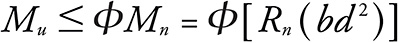
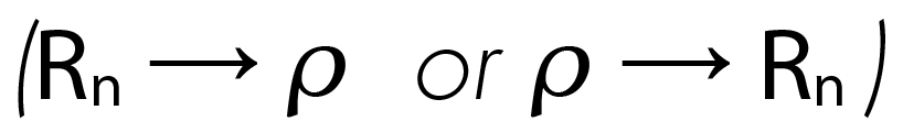
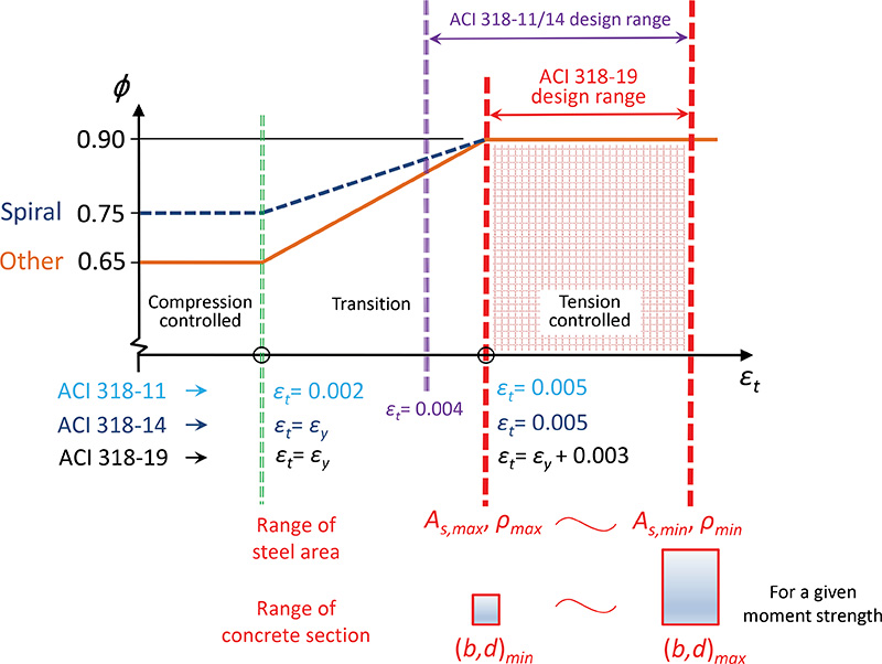
Figure 1 shows the relationship between 𝜌, Rn, and section size (b, d ). To start the design with a given concrete section size (b, d ), the calculation is carried out from right to left, and Rn ⟶ 𝜌 is needed to determine the required steel area. If a target reinforcement ratio is adopted to start the design, the computation is performed from left to right and 𝜌 ⟶ Rnis required to determine a concrete section size (b, d ).
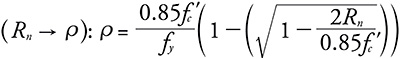
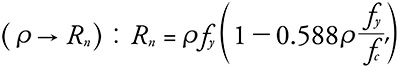
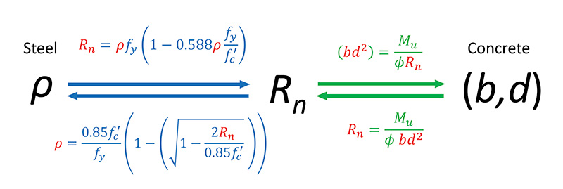
Figure 1 Singly reinforced rectangular section
ACI 318-19
The trade-off concept of the reinforcement ratio and the concrete section size can be seen in Figure 2. To provide the same moment strength in Eq. (1), the maximum reinforcement requirement (ACI 318-19: 9.3.3.1) corresponds to the smallest required concrete section, whereas the minimum reinforcement limit (ACI 318-19: 9.6.1.2) corresponds to the largest concrete section. Therefore, the ACI 318-19 range of reinforcement ratio (𝜌max − 𝜌min) can be used to determine the range of concrete section size ((b, d )min − (b,d )max). For practical design purposes, a concrete section size in the range shall be selected to design the section to support the required moment strength while meeting the ACI reinforcement requirements. If a design ends up being a transition section (𝜀y < 𝜀t < 𝜀y + 0.003) rather than a tension-controlled section, it is clear that the concrete section size (b, d ) is too small, and a larger section size shall be provided to ensure the design is in the range.
More Complex Sections
One straightforward method for designing complex singly reinforced or doubly reinforced concrete beam sections is to separate the beam section into multiple sections and add their moment strengths together. Tension steel is assumed to yield for design purposes.
Singly Reinforced Beam Sections
For a singly reinforced non-rectangular beam section, the design flexural strength can be determined based on breaking down the equivalent concrete compression zone, Ac, into multiple smaller areas (such as rectangles) and adding their design strengths, as
𝜙Mn = ∑𝜙Mn
(4)
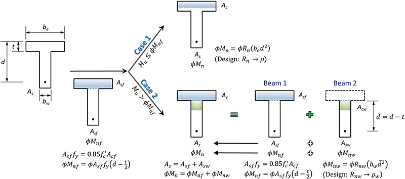
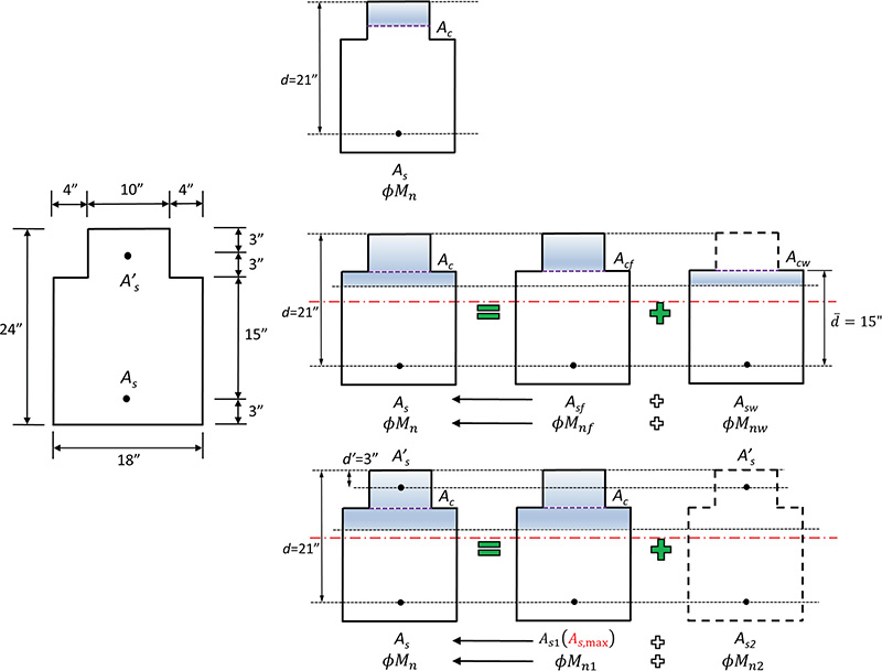
As a simple example, Figure 3 shows two cases of a T-beam. The design of a Case 1 T-beam is essentially the same as the design of a rectangular section (Rn ⟶ 𝜌). For a Case 2 T-beam, the total flexural strength can be written by adding the strength provided by the flange (Beam 1, with steel area Asf ) and the web (Beam 2, with steel area Asw ), as
𝜙Mn = 𝜙Mnf + 𝜙Mnw
(5)
Once the moment strength of the flange, 𝜙Mnf , is determined, the leftover factored moment shall be supported by the web and used to design the web as a rectangular section (Rnw ⟶ 𝜌w). Rnw and 𝜌w are the flexural-resistance factor and reinforcement ratio of the web, respectively.
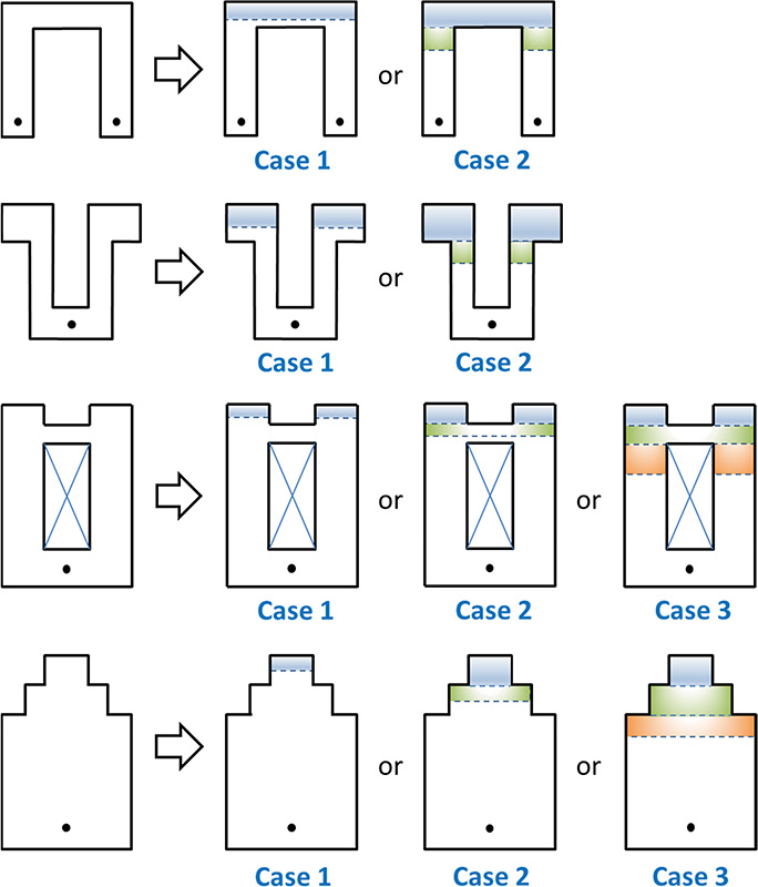
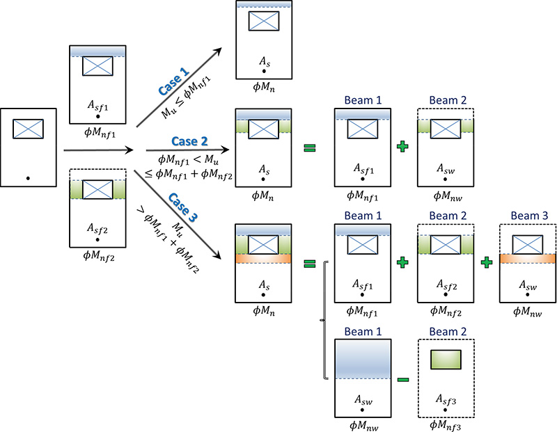
The same concept can be applied to more complex cross-sections, and different design cases may be possible. Some more examples are shown in Figure 4. Some detailed calculations are needed to determine which case is required for the given factored moment. Figure 5 details how to decide the three possible design cases of a beam section with a void and how to further separate the beam section into multiple sections (2 or 3 beam sections in this example). A Case 2 beam here is similar to a Case 2 T-beam mentioned before, so that As = Asf 1 + Asw and 𝜙Mn = 𝜙Mnf 1 + 𝜙Mnw. For a Case 3 beam in this example, the total required steel area and design moment strength are As = Asf 1 + Asf 2 + Asw and 𝜙Mn = 𝜙Mnf 1 + 𝜙Mnf 2 + 𝜙Mnw , respectively. An alternative way to design a Case 3 beam is to use As = Asw − Asf 3 and 𝜙Mn = 𝜙Mnw − 𝜙Mnf 3 , where Asf 3 and 𝜙Mnf 3 are the steel area and design moment strength, respectively, corresponding to the void (minus for negative values). Dividing the equivalent concrete compression zone into multiple areas is a general approach and is easily applicable as long as the web (Asw and 𝜙Mnw) can be designed as a rectangular section (Rnw ⟶ 𝜌w).
Doubly Reinforced Beam Sections
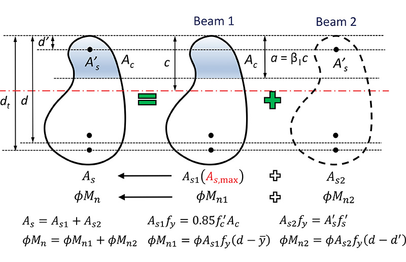
Figure 6 illustrates separating a doubly reinforced beam section into two beam sections. If the upper bound (maximum) design moment strength of a singly reinforced beam section (𝜙Mn1 = 𝜙Mn,max) is still not adequate to support the factored moment, Mu, a doubly reinforced beam section becomes necessary (for the same section size). The maximum area of reinforcement, As,max , permitted by ACI 318-19 for a singly reinforced beam section is determined first using 𝜀t,min = 𝜀y + 0.003 before the maximum moment strength can be calculated. This is noted as Beam 1. A backward analysis is required here and applies to any cross-sectional shape. The leftover factored moment has to be supported by Beam 2, which is provided by the couple of additional tension and compression steel (As2 & A’s). Although it is acceptable to design a doubly reinforced beam section targeting a strain value greater than 𝜀t,min , the design using 𝜀t,min would result in the least total area of steel in the section.
Section Design Procedure
For a given beam section, the design procedure includes the following steps:
1.Perform a backward analysis (see Part 1: Section Analysis) to determine the maximum area of reinforcement, As,max, allowed in a singly reinforced beam section
𝜀t,min = 𝜀y + 0.003 ⟶ c (neutral axis) ⟶ α = 𝛽1c ⟶ Ac
(shape) ⟶ As,max = ![]()
2.Determine the maximum design moment strength, 𝜙Mn,max (or 𝜙Mn1), when As,max is used in the beam section y(shape) ⟶ Mn,max ⟶ 𝜙 ⟶ 𝜙 Mn,max
3.Determine the design of a singly reinforced or doubly reinforced section. If Mu ≤ 𝜙Mn,max, design the section as a singly reinforced concrete section; proceed with steps 4a-8a. If Mu > 𝜙Mn,max), design a doubly reinforced beam section. Determine the leftover moment, Mu2 = Mu − 𝜙Mn,max, and proceed with steps 4b-8b.
4a.For a singly reinforced beam section, determine the moment resistance of the flange![]() (6)
(6)![]() (7)
(7)
5a.Determine the design case of a singly reinforced beam section. If Mu ≤ 𝜙Mnf , design the section as a Case 1 beam. This is essentially the design of a rectangular section with b = be .![]() select bars and perform a final check.
select bars and perform a final check.
If Mu > 𝜙Mnf , design a Case 2 beam. Calculate the leftover moment, Muw = Mu − 𝜙Mnf , and proceed with steps 6a-8a.
6a.Design the web as a rectangular section, i.e., b = bw, and d is the distance from the centroid of the tension steel group to the extreme concrete compression fiber in the web.![]()
7a.Calculate the total steel area for flange and web, As = Asf + Asw
8a.Select rebars and perform a final check. Here steps 4a-8a are written assuming a Case 2 beam. Similar steps can be followed for a more complex case (e.g., Case 3).
4b.Check whether the compression steel yields.
Calculate![]()
and check whether this is greater than or equal to the yield strain of steel, 𝜀y .
Calculate the compression steel stress
f’s = Es 𝜀‘s (does not yield) or fy (yield)
5b.For Beam 2![]() (8)
(8)
Calculate tension steel area in Beam 2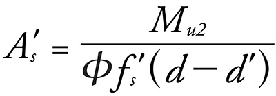 (9)
(9)
6b.Calculate compression steel area in Beam 2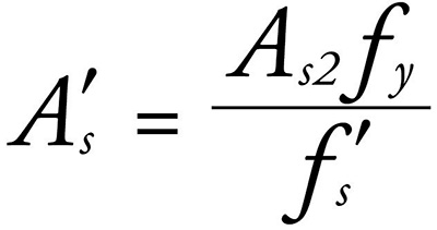 (10)
(10)
or![]() (11)
(11)
7b.Compute total tension steel area
As = As1 (As,max) + As2 (12)
and total compression steel area A’s (in step 6b).
8b.Select tension and compression rebars, and perform a final check.
A Numerical Example
Given a beam section, as shown in Figure 7, use f’c = 3,000 pounds per square inch (psi) and Grade 60 rebars (fy = 60 kips per square inch [ksi]). Determine the minimum required steel areas to support the following factored bending moments and select rebars.
a. Mu = 120 kips − feet (k − ft.);
b. Mu = 220 k − ft;
c. Mu = 280 k − ft.
Bending Moment, Mu = 120 k − ft
1.Perform a backward analysis (detailed calculations are skipped here; see the numerical example in Part 1: Section Analysis in a previous issue of Structure Magazine) to find the neutral axis depth, c, and determine As,max for a singly reinforced beam section.
c = 7.875 inches (in)
As,max = 3.08 square inches (in2)
2.The maximum design moment strength
𝜙Mn,max = 241 k − ft
3.Since Mu = 120 k − ft < 𝜙Mn,max = 241 k − ft, design the section as a singly reinforced concrete section.
4a.For a singly reinforced beam section, determine the moment resistance of the flange![]()
![]()
5a.Since Mu = 120 k − ft < 𝜙Mnf = 206.55 k − ft, design the section as a Case 1 beam (a rectangular beam section with b = be = 10 in).![]()
![]()
As = 𝜌be d = 0.00655 × 10 in × 21 in = 1.38 in2
This is the minimum required steel area to support the factored moment.
Select 5 #5 bars in one row; As = 0.31 × 5 = 1.55 in2, in the range of steel area permitted by ACI 318-19 for a singly reinforced beam section (1.26 in2 – 3.08 in2).
8 steps of forward analysis as introduced in Part 1: Section Analysis of the article are conducted to perform a final design check. It is confirmed to be a tension-controlled section (𝜙 = 0.9), and 𝜙Mn = 134 k − ft > Mu = 120 k − ft. Strength is ok.
Bending Moment, Mu = 220 k − ft
3.Since Mu = 220 k − ft < 𝜙Mn,max = 241 k − ft, design the section as a singly reinforced concrete section.
5a.Since Mu = 220 k − ft > 𝜙Mnf = 206.55 k − ft, design the section as a Case 2 beam by separating the beam section into 2 sections.
Leftover moment Muw = Mu − 𝜙Mnf = 220 − 206.55 = 13.45 k − ft
6a.Design the web as a rectangular section with b = bw = 18 in and d = d − t = 21 − 6 = 15 in![]()
![]()
![]()
Asw = 𝜌wbwd = 0.0007445 × 18 in × 15 in = 0.20 in2
7a.Total steel area for flange and web, As = Asf + Asw = 2.55 + 0.20 = 2.75 in2
This is the minimum required steel area to support the factored moment.
8a.Select 5 #7 bars in one row; As = 0.6 × 5 = 3.0 in2, in the range of steel area permitted by ACI 318-19 for a singly reinforced beam section (1.26 in2 – 3.08 in2).
8 steps of forward analysis are conducted (see Part 1: Section Analysis) to perform a final design check. It is confirmed to be a tension-controlled section (𝜙 = 0.9), and 𝜙Mn = 236 k − ft > Mu = 220 k − ft. Strength is ok.
Bending Moment, Mu = 280 k − ft
3.Since Mu = 280 k − ft > 𝜙Mn,max = 241 k − ft, design the section as a doubly reinforced concrete section.
Leftover moment Mu2 = Mu − 𝜙Mn,max = 290 − 241 = 39 k − ft
4b.Check whether the compression steel yields![]()
Compression steel stress
f’s = Es 𝜀‘s = 29,000 ksi × 0.001857 = 53.86 ksi
5b.For Beam 2
Mu2 = 𝜙[As2 fy (d − d’ )]
Tension steel area in Beam 2![]()
6b.Compression steel area in Beam 2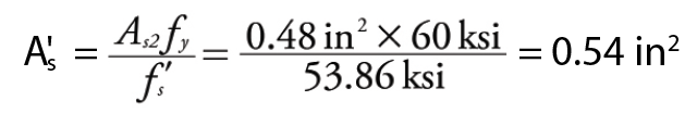
7b.Total tension steel area
As = As1 (As,max) + As2 = 3.08 + 0.48 = 3.56 in2
Total compression steel area A’s = 0.54 in2
8b.Select rebars
tension 6 #7 bars in one row, As = 0.6 × 6 = 3.6 in2
compression 2 #5 bars in one row, A’s = 0.31 × 2 = 0.62 in2
12 steps of forward analysis are conducted (see Part 1: Section Analysis) to perform a final design check. It is confirmed to be a tension-controlled section (𝜙 = 0.9), and 𝜙Mn =284 k − ft > Mu = 280 k − ft. Strength is ok.
Summary
1.Although, in practice, structural engineers can use approximations to design beam sections (for example, a box section is approximated as a rectangular section), the design is handled on a case-by-case basis. A general framework for the design of singly reinforced and doubly reinforced concrete beam sections is presented in this article. The approach is rigorously derived and is used to find the minimum required steel area to support a given factored bending moment.
2.Separating the equivalent concrete compression zone into multiple smaller areas is very useful and can be applied to more complex cross-sections.
3.The backward analysis to determine the maximum steel area and bending moment strength of a singly reinforced beam section permitted by ACI 318-19 helps design doubly reinforced beam sections.
4.This article is supplementary material to any reinforced concrete textbook to understand the topic better.
References
ACI (American Concrete Institute). 2011. Building Code Requirements for Structural Concrete and Commentary. ACI 318-11, Farmington Hills, Michigan.
ACI (American Concrete Institute). 2014. Building Code Requirements for Structural Concrete and Commentary. ACI 318-14, Farmington Hills, Michigan.
ACI (American Concrete Institute). 2019. Building Code Requirements for Structural Concrete and Commentary. ACI 318-19, Farmington Hills, Michigan.
McCormac, J. C., Brown, R. H. 2015. Design of Reinforced Concrete, 10th Edition. Wiley, Hoboken, New Jersey.