
What is Ultrasonic Testing?
When doctors need to diagnose an internal medical issue, they use an X-ray machine or ultrasonic testing to non-invasively look inside the human body. When it comes to checking the potentially ailing components of a bridge, the engineers can use ultrasonic testing (UT), a non-destructive testing (NDT) method, to look inside the bridge. This allows them to view and understand a bridge’s welds and components for structural integrity before deterioration or internal flaws become a potential hazard.
Ultrasonic testing is a non-invasive testing practice that is widely used for evaluating the integrity and condition of bridge pins, gusset plates, and welds. Pins, gusset plates, and welds are critical components of any bridge as they are responsible for transferring loads from one member to another and helping to stabilize the entire structure. This article primarily addresses the UT inspection of bridge pins, as UT inspections of welds is relatively straightforward (generally following ASNT, or AWS D1.1 or D1.5), whereas UT inspection of bridge pins is not as clear (generally following the guidelines of FHWA HRT 04-042). Using a transducer (transmitting and receiving high-frequency sound), UT employs a mechanically induced sound wave to inspect the material properties of these components in order to identify any weaknesses, defects, wear, or flaws that could compromise the safety of the bridge. Findings may include internal cracks, internal inclusions, hidden surface wear, and other types of defects that may not be visible to the naked eye. Once detected, the findings must be evaluated to determine the potential severity of each identified issue.
One of the main advantages of ultrasonic testing is that it allows engineers to examine the internal and hidden external areas relatively quickly and efficiently with minimal disruption to the bridge’s operations for its public users. Engineers can then identify and monitor advancing issues or direct repairs in an efficient and accurate manner.
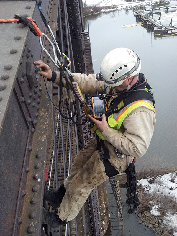
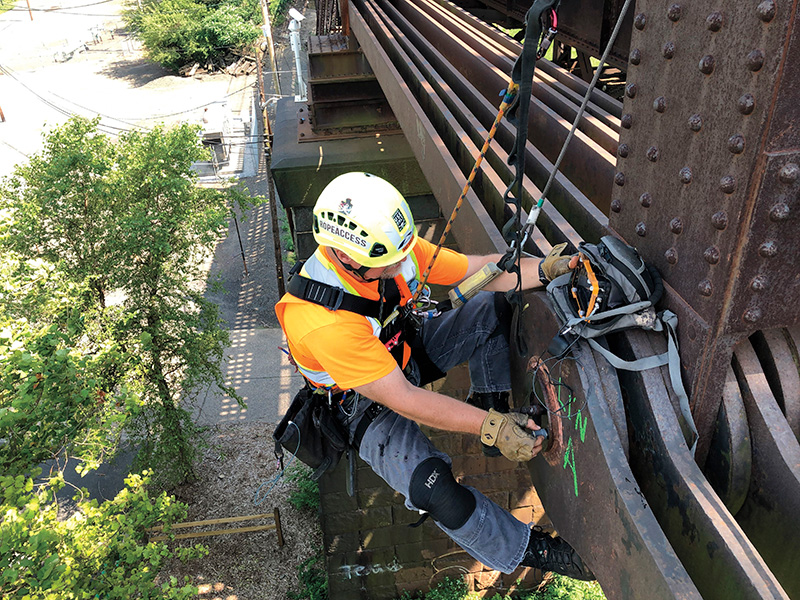
Photo courtesy of Modjeski and Masters, Inc.
How does Ultrasonic Testing Work?
A UT inspection requires an experienced UT technician and an ultrasonic flaw detector machine known as an ultrasonic transducer. The machine transmits high-frequency sound waves into the material being tested. When the sound waves encounter a discontinuity (flaw or boundary) in the material, they are reflected back to the transducer. The flaw detector processes the time of outgoing and reflected sound waves into an electrical signal displayed on a screen for the operator to interpret. The UT flaw detection equipment measures the time between the outgoing and incoming signals and converts the time into a “distance” by means of machine settings or calibration settings. In this way, a flaw detector machine can be thought of as a “fancy stopwatch” that converts time into distance through specific machine settings. The calibration settings of the machine will greatly affect the accuracy of the results read on the operator’s screen.
UT inspection of bridge pins uses very precise UT flaw detection equipment to examine an inexact medium (bridge components) under field conditions. For example, all boundary surfaces are neither truly flat nor uniformly smooth, and reflective surfaces can be at a variety of sizes and angles. A qualified UT technician is capable of using the transducer to measure bridge pin length and distance to reflectors with incredible accuracy, provided reflector conditions are precise. To ensure the results are accurate, there is a requirement of proper calibration settings and reflectors perfectly perpendicular to the direction of the sound waves, as well as an experienced UT technician to interpret the findings. This is why it is important for the operator to thoroughly understand what they are examining. In the case of bridge pins, the types of pins (straight or shouldered) on a particular bridge can affect what the operator will see on their screen. The geometry of bridge pins varies and dictates which transducer(s) must be used during the process. Geometric oddities in the pin could be misinterpreted if improperly read, which could result in a compromised report, or at the very least, frustration for all involved. There is almost as much art as there is science when it comes to the interpretation of UT results; thus, it is important to have an experienced individual perform the UT.
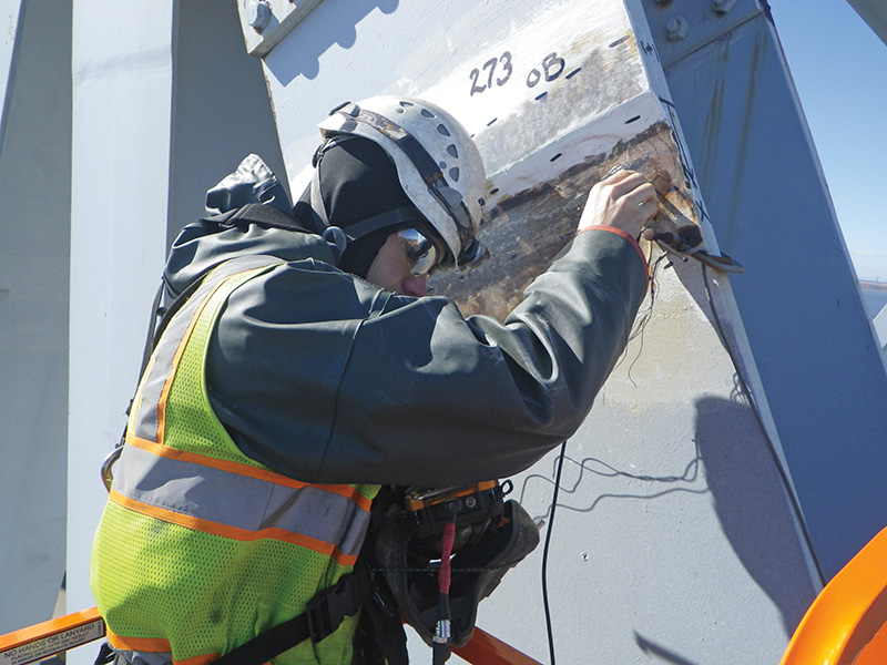
Photo courtesy of Modjeski and Masters, Inc.
Although ultrasonic testing is a complex process as it involves a deep understanding of several factors from engineering to physics, it can be considered as a learned art. The “art” is found in the interpretation of return signals—a skill gained through an understanding of UT sound wave propagation, a foreknowledge of what might be observed based on pin geometry, personal experience, and even the history of the bridge. The UT operator must pay close attention to the dynamics of return signals and document the test through detailed data sheets to be used for later comparisons.

A good UT inspection is also not complete without proper documentation. Documentation should include data sheets, sketches, and saved versions of pertinent screenshots (A-scans). The dynamic and A-scan return signals obtained during a bridge pin inspection are what help engineers evaluate the UT operator’s interpretation. It also allows other UT technicians to be able to relocate the indications for verification and comparative analysis. An often glossed-over component, documentation is critical to a successful inspection.
A successful UT inspection was performed on a steel truss bridge constructed in 1909 across the Mississippi River, designed by Modjeski and Masters. During a detailed inspection in 2007, 204 truss joint/hanger pins were evaluated with findings of surface corrosion, wear grooves, and gaps observed within the hanger pin assemblies. Ultrasonic testing revealed discontinuities of varying degrees in most of the pins, including verification of visible wear grooves, identification of hidden wear grooves, areas of hidden corrosion, and identification of internal flaws (likely present from the pin formation process). 28 of the 204 pins were found to have significant ultrasonic indications (warranting future monitoring), and three were found to have surface flaws. The non-invasive nature of UT allowed the technicians or the engineers to diagnose potential issues and flaws before they compromised the structure and became a danger to the public.
Types of Ultrasonic Testing Techniques
Ultrasonic testing can be conducted using several different techniques, each of which is suited to different types of structures and applications. The most common method used for bridge pins is pulse-echo testing, which involves sending a pulse of ultrasonic energy through the material and measuring the time it takes for the pulse to reflect back. The speed of the pulse and the time it takes to return can be used to calculate the thickness and density of the material, as well as to identify any flaws or defects that may be present. Pulse-echo testing is relatively simple and can be used on a wide range of materials, including metals, plastics, and ceramics.
Through-transmission testing is another method where ultrasonic energy is transmitted through one side of the material and received on the other side, and the intensity of the energy that passes through the material is measured. This method is particularly useful for dense or multi-layered materials as it allows engineers to examine the entire thickness of the material.
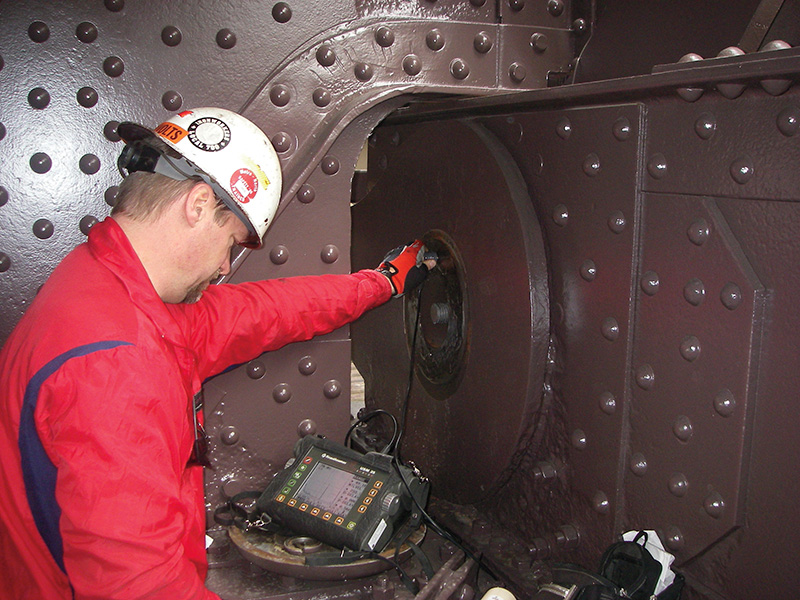
Photo courtesy of Modjeski and Masters, Inc.
Time-of-flight diffraction (TOFD) is a specialized method that involves sending ultrasonic energy through the material and measuring the time it takes for low amplitude energy to defract (bend around) any flaws or defects that may be present. The full potential of TOFD for characterizing defects can only be realized if the amplitude and phase of the defracted ultrasound can be reliably interpreted. TOFD is particularly useful for detecting the ends of cracks and other types of defects that may be difficult to identify using other testing methods.
In addition to these techniques, there are also several other specialized methods that can be used for more specific applications. For example, phased array ultrasonic testing involves using multiple ultrasonic transducers simultaneously to create a two-dimensional image of the material being tested, which can be used to more accurately locate and characterize defects. Other specialized techniques include laser ultrasonic testing, which uses laser pulses instead of sound waves, and thermoelastic stress analysis, which involves measuring temperature changes in the material to identify stress concentrations.
Limitations of Ultrasonic Testing
One of the challenges of ultrasonic testing is that it requires specialized equipment and trained and experienced technicians to carry out the inspection process. This means that it may not always be practical or cost-effective to use ultrasonic testing as the primary method of evaluating structural integrity; however, for firms or organizations that have access to the resources and expertise to carry out proper ultrasonic testing, it can be an invaluable tool for ensuring the safety and reliability of bridge components.
Another challenge with ultrasonic testing is the orientation of discontinuities and surface boundaries. Ultrasonic testing is most effective at detecting reflectors that are perpendicular to the direction of the sound waves. Discontinuities that are oriented parallel to the sound waves may be more difficult to detect. Angular discontinuities can deflect sound and may require changes in the type of transducer used.
Temperature can also be a challenge during an inspection. Interestingly, the speed of sound waves can change with temperature. This can affect the accuracy of a UT inspection given that it relies on these waves for an accurate reading. If the temperature poses an issue, the UT operator may need to change the frequency used to push sound through the component. This creates more beam spread, which picks up more area than desired and reduces the clarity and detail of the inspection.
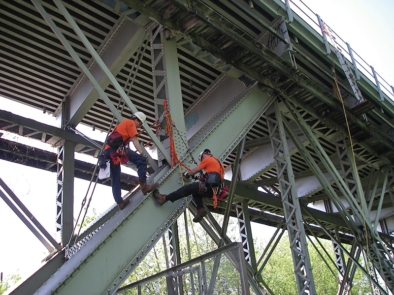
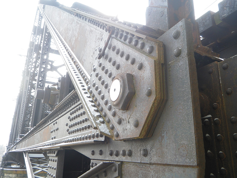
Photo courtesy of Modjeski and Masters, Inc.
Certifications
There are several levels of certification available to those who are interested in performing ultrasonic testing in their work. These levels are recognized internationally and defined in the United States by the American Society for Nondestructive Testing (ASNT).
Level I is the entry-level certification for UT technicians. It allows the individual to set up and calibrate equipment, perform basic UT examinations, and prepare reports under the supervision of a Level II or Level III technician.
A Level II technician is able to independently set up and calibrate equipment, perform basic and advanced UT examinations, prepare reports, and provide guidance to Level I technicians under a specific procedure approved by a Level III technician.
A Level III technician is able to perform all tasks of a Level II technician, as well as develop and implement UT procedures, select and justify the use of UT techniques, and provide guidance to Level I and Level II technicians.
When selecting an inspector for the job, bridge owners should carefully consider the experience and qualifications of a technician, as well as their certification level. It’s possible for an individual to be certified in UT but not be prepared to thoroughly and accurately inspect all types of bridge pins. Experience is key—training and certifications do not replace a UT technician versed in examining the intricacy of bridge pins and their unique properties.
The Future of Ultrasonic Testing
There are several trends and developments that are shaping the future of ultrasonic testing and helping the field evolve. Artificial intelligence (AI) is one of the ways machine learning is being used to improve the accuracy and efficiency of UT. For example, AI algorithms can be used to analyze large amounts of test data and identify patterns that may indicate the presence of defects. They can also be used to optimize testing parameters and improve the reliability of test results.
Another developing trend is 3D imaging. It is the process in which one can generate 3D images of the material being tested. These images can provide more detailed and accurate information about the size, shape, and location of defects within the material.
There are developments in no-contact ultrasonic testing methods that do not require the use of a physical transducer to transmit ultrasonic waves. These methods could be used to test materials or components that are sensitive to physical contact or to test structures that are too large or complex to be tested with traditional UT methods. Researchers are also working on the development of wireless UT systems, which could be used to test structures or components in hard-to-reach or hazardous locations. These systems would use wireless sensors and communication technologies to transmit test data remotely. Acoustic emission testing is a related technique that involves detecting and analyzing the sounds generated by defects or material failures. Researchers are working on integrating acoustic emission testing with UT to provide a more comprehensive understanding of the condition of a material or component. At this time, extensive calibration is required.
Since its inception more than 80 years ago, ultrasonic testing remains the most valuable and reliable tool for evaluating the condition of bridge pins, welds, and gusset plates. With the depth of knowledge that goes into the inspection of these vital components—along with the promising future of technology and its role in engineering—ultrasonic testing continues to minimize the risk of failure and ensure the safety and reliability of our everyday bridges.