
Updates to the Building Code Requirements for Masonry Structures.
The 2022 TMS 402 Building Code Requirements for Masonry Structures added Appendix D for glass fiber reinforced polymer (GFRP) reinforced masonry. GFRP reinforcement is non-corrosive, non-conductive, and not thermally conductive, so there is no thermal bridging. Due to these properties, GFRP reinforcement is advantageous in the masonry near electromagnetic equipment, such as MRI rooms in hospitals and masonry walls near high-voltage cables and transformers in substations. Other applications include walls exposed to severe environments, such as in coastal construction, seawalls, and chemical plants. The lightweight nature of the GFRP bar, being one-fourth the steel weight, allows for production efficiencies for the contractor and health and safety benefits to workers.
Scope
TMS 402 Appendix D is for solid, straight, and bent GFRP bars used as internal reinforcement in grouted concrete or clay masonry. Appendix D only applies to the design of masonry walls that do not support axial compressive, allowable stress-level loads of more than 200 lb/linear ft (2919 N/m) in addition to their weight, and lintels within such walls. In other words, Appendix D provides provisions for non-load-bearing partition walls and retaining walls. In addition, GFRP-reinforced walls are limited to non-participating walls in Seismic Design Category C or less. As additional research becomes available, the goal is to expand Appendix D and remove some current restrictions.
Material Properties
There are three key material properties of GFRP bars to be used as flexural reinforcement: tensile strength, modulus of elasticity, and tensile strain at ultimate. ASTM D7957, Standard Specification for Solid Round Glass Fiber Reinforced Polymer Bars for Concrete Reinforcement, provides minimum values for these material properties. Due to the linear nature of GFRP reinforcement, the tensile strain at the ultimate can be taken as the tensile strength divided by the modulus of elasticity. The minimum values from ASTM D7957 can be used for design when the GFRP bar manufacturer is unknown. However, many manufacturers make bars that significantly exceed the minimum values. The designer should select and consult with the manufacturer to determine the actual material properties of bars that will be specified for the project. Improvements in manufacturing and materials have resulted in second-generation GFRP bars with higher strength and higher stiffness. Using these GFRP bars can result in much more efficient designs. It is to be noted that a GFRP bar presents a linear elastic behavior to failure with Young’s modulus of about one-quarter that of steel. Additionally, its transverse properties are resin dominated and, for that, significantly lower than that of steel.
Development and Splice Length
The development length of GFRP bars in masonry is taken as the development length in ACI 440.11-22 Building Code Requirements for Structural Concrete Reinforced with Glass Fiber Reinforced Polymer (GFRP) Bars (2022). For steel reinforcement, the lap splice length is equal to the development length in TMS 402. For GFRP bars, the lap splice length is 1.3 times the development length to match ACI 440.11. Testing was performed to validate using the ACI 440.11 equation for masonry. The testing indicated that using the ACI 440.11 tends to be conservative for masonry; however, sufficient testing was not available for the committee to develop a new equation. Somewhat counterintuitively, development and splice lengths tend to be smaller in masonry than in concrete for the same compressive strength. This is due to the masonry grout having a smaller aggregate size and high slump, resulting in a better encasement and better bond to the reinforcement.
Flexural Strength
The flexural strength will either be controlled by the tensile strength of the GFRP reinforcement or the compressive strength of the masonry. Due to the high strength of the GFRP reinforcement, the section will often be controlled by the strength of the masonry.
When the masonry controls the strength, the stress in the GFRP reinforcement will be less than the design strength. Similar to an “over-reinforced” steel reinforced section where the stress is below yield, the stress in the GFRP reinforcement can be obtained as the solution to a quadratic equation.
A key difference between steel reinforcement and GFRP bars is the failure mechanism of the reinforcement. Instead of yielding, GFRP bars fail in rupture before the masonry’s ultimate compressive strain is achieved for the case of “under-reinforced” sections. Therefore, the depth of the neutral axis is unknown at failure when the GFRP reinforcement controls the strength, and the assumption of an equivalent rectangular stress block is inappropriate. In lieu of a more detailed analysis, which can become quite complex, TMS 402 conservatively permits an equivalent compression stress block based on the depth to the neutral axis corresponding to the balanced condition.
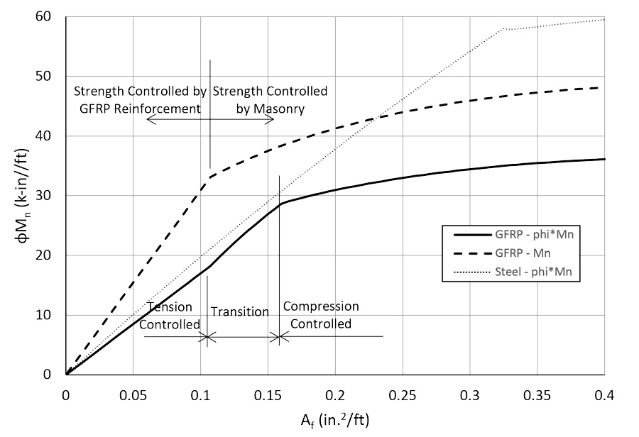
While a masonry crushing failure mode can be predicted based on calculations, the member, as constructed, may not fail accordingly. For example, if the masonry strength is higher than specified, the member can fail due to GFRP rupture. For this reason, a compression-controlled section is defined as a section in which the strain in the GFRP reinforcement is 80% or less than the design strain at GFRP failure. The strength-reduction factor for sections controlled by the GFRP reinforcement, or tension-controlled sections, is 0.55. The strength-reduction factor for a compression-controlled section is 0.75. A linear transition region is used between tension and compression-controlled sections or for a GFRP strain at the ultimate of between 80 and 100% of the design strain. Figure 1 shows the nominal moment strength and the design moment strength (strength-reduction factor times the nominal strength) for an 8-inch concrete masonry wall with centered reinforcement and a masonry compressive strength of 2,000 psi as a function of the area of reinforcement. The design strength for Grade 60 steel reinforcement is also shown for comparison.
Wall Deflections
The horizontal deflection of walls under allowable stress level loads is limited to 0.01 times the height of the wall. This deflection limit is 42% higher than the deflection limit for steel-reinforced masonry walls of 0.007 times the height of the wall. A wall loaded in this range returns to its original vertical position when the lateral load is removed. With GFRP reinforcement, the wall will remain elastic at much higher deflection levels than walls with steel reinforcement.
GFRP-reinforced masonry walls have a lower stiffness than steel-reinforced walls. This leads to increased second-order, or P-delta, effects. The second-order moment can be 30-50% of the first-order moment with GFRP-reinforced walls. Using second-generation higher stiffness GFRP bars can result in a significant reduction in the second-order moment.
Shear Strength
Due to a lack of research on the shear strength of GFRP-reinforced masonry members with or without shear reinforcement, the contribution of GFRP shear reinforcement is not quantifiable at this time, and all shear is required to be taken by the masonry. The nominal shear strength due to the masonry of GFRP-reinforced masonry members is taken as one-half the nominal shear strength of masonry with conventionally reinforced masonry members. The 0.5 factor is due to GFRP-reinforced members typically having a smaller depth to the neutral axis than steel-reinforced members with equal areas of reinforcement due to the lower modulus of elasticity of GFRP reinforcement as compared to steel reinforcement. This reduces the depth of the compression region and increases crack widths, thereby reducing the amount of interlocking aggregate under compression. Also, the contribution of dowel action of longitudinal GFRP reinforcement has yet to be determined. Shear rarely controls walls under out-of-plane loads, which primarily affects lintel design.
Lintels
Masonry has a lower masonry compressive strength parallel to the bed joint than perpendicular to the bed joint. This will affect lintel design when the strength is controlled by masonry. To account for this, a χ factor is used, with the masonry stress over the equivalent compression stress block being 0.80χf’m, where f’m is the specified compressive strength of the masonry (determined with the load perpendicular to the bed joint). The values of χ are taken from the Canadian Masonry Code (CSA S304.1-14). The value of χ is 0.5 when the grout is not horizontally continuous in the compression zone, and χ is 0.7 when the grout is continuous horizontally in the compression zone. An example of the grout not being horizontally continuous would be the compression zone constructed of standard stretcher units with full-height webs. Head joints break up the grout core. An example of the grout being continuous horizontally would be the compression zone constructed of knock-out bond beam blocks, allowing the grout to be continuous across head joints.
When the strength is controlled by the masonry, χ significantly impacts the strength. When the strength is controlled by the reinforcement (either steel or GFRP), the compressive strength of the masonry has minimal effect on the nominal moment strength because the depth of the neutral axis is minimized. Thus, χ has minimal impact and is not needed in the design.
Creep Rupture
Creep rupture or static fatigue is a phenomenon that occurs in GFRP bars when the bar suddenly ruptures after being subjected to constant tension over a given period. Creep rupture can control retaining walls, where the entire load is sustained. To avoid creep rupture of GFRP bars, the sustained stress under allowable stress level loads is limited by TMS 402 Section D.5 to 30% of the design tensile strength of the bar.
Conclusions
The addition of Appendix D to TMS 402 is a significant advancement for masonry and composite reinforcement. The TMS 402/602 code committee accomplished the goal of adding composite reinforcement to the code. There is still work to be done to remove some of the current restrictions and to take advantage of continued research and product development to make designs more efficient. This is a major priority of the 2028 code committee.■