
Othmar Ammann’s George Washington Bridge, NYC
The many 19th century engineering design-proposals to span the Hudson River between New York City and New Jersey reveal a progressive shift from heavy rail-bridge designs to lighter bridges, as the era burst into the vehicle age in the 1920s. Before then, ferries and car floats transferred freight, horse-drawn carriages, goods, and a few “horseless carriages” across the Hudson River to and from Manhattan, to connect with various rail companies to complete the land transport. With suburban development, combined with the popularity of the automobile, a public outcry developed for the expansion of roads and bridges.
To meet such demands, the Port of New York Authority (PNYA), established in 1921, acted quickly to organize a bridge division to design many new bridge projects. One project was Othmar Ammann’s (1879-1965) 1924 bridge design for an uptown steel “Hudson River Suspension Bridge” at 179th Street, to connect New York City to Fort Lee in New Jersey, later known as the George Washington Bridge. The U.S. War Department approved the design for a center-span of about 3500 feet suspended between two tower piers set close to each shoreline, a 4760-foot long span between anchorages, and a deck elevation of 235 feet above mean high water (MHW). The main span was over twice the length of any previous suspension bridge, and the number of traffic lanes even today surpasses any other suspension bridge in the world.
Thorough traffic-count studies to justify the need for a bridge in the 1920s accurately predicted an annual bridge usage of eight million vehicles by the 1931 opening, but this largest bridge-building undertaking in history was effectively designed for a capacity of over 50 million, reached in 1960. Today’s actual annual traffic count is about 110 million.
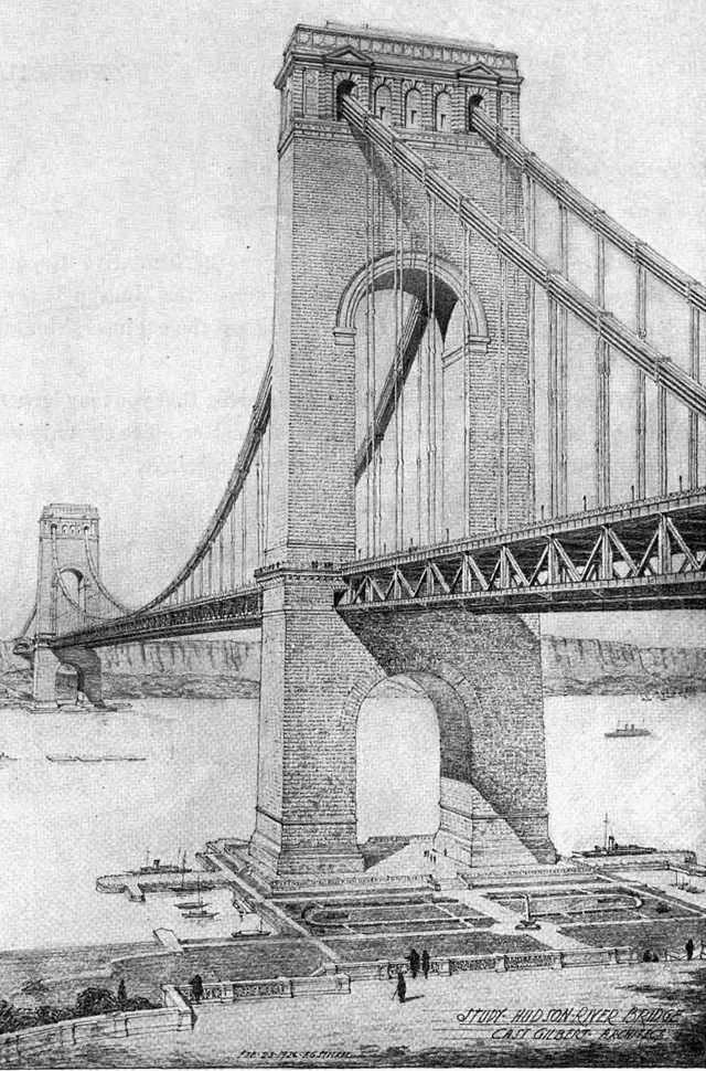
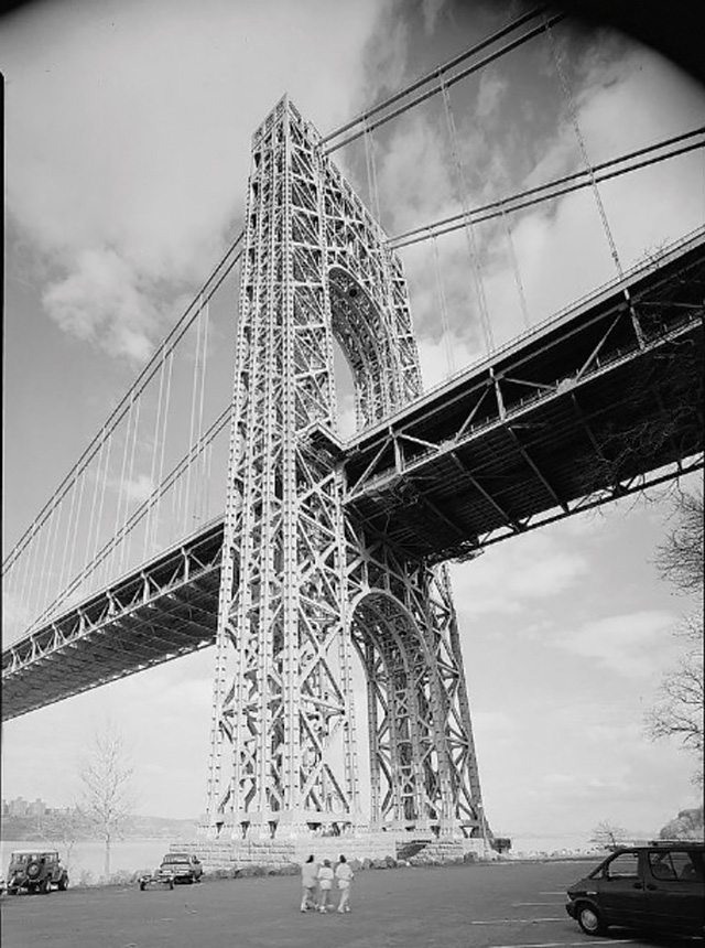
The original design intention for the George Washington Bridge consisted of four huge masonry-covered steel space-frame towers, the tops of which soar over 630-feet high above MHW. Original plans included a reinforced concrete encasement, with or without a granite facing, to be constructed over the monumental steel-skeleton towers. Drawings show a masonry bridge with an arched portal above and below the deck, and a thin, modern-appearing deck. But when the bridge opened in 1931, it was without the masonry encasement, and without a planned observation deck and restaurant at the tops of the towers.
The New Jersey and New York legislatures amicably established legal and financial support for the bridge. The $55 million-dollar projected construction cost – with the highest cost attributed to real estate – came in under budget and the bridge opened before the projected opening date. Tolls readily paid back all debt, as the area population nearly doubled in the 1920s. The bridge today is owned and operated by the Port Authority of New York and New Jersey (PANYNJ).
Background & Theory
Othmar Ammann first studied architecture in his native Zurich before switching to engineering studies at the Swiss Federal Institute of Technology, graduating in 1902. He then immigrated to New York in 1904. Wilhelm Ritter (1847-1940) was one of Ammann’s professors: From him, Ammann learned to physically test models, and, at the same time, compare test findings with that era’s early scientific calculations to predict general structural behavior. Ritter understood and taught French engineer Claude L.M. Navier’s (1785-1836) 1823 observation that the greater the dead weight and length of a suspended span, the lesser the need for the standard, heavy allowances in deck stiffness. With these thoughts in mind, Ammann designed a deck vertical height-to-span ratio of 1/350 for the bridge, rather than the standard-to-date ratio of 1/60 for shorter long-span suspension bridges. The extreme ratio worked due to the superstructure’s great weight and length stiffening effect. Ritter also emphasized aesthetics and Ammann shared that aspiration, leading him to seek a masonry exterior to the towers.
Tower Foundations
The tower foundation rests on solid Manhattan schist near the New York shore. The New Jersey foundations rest on sandstone 70 feet from the shore. Soil boring cores taken at the tower bases tested at 12,000-15,000 pounds per square inch (psi) average compressive strength, about 30 times the expected maximum tower-base pressure.
Anchorages
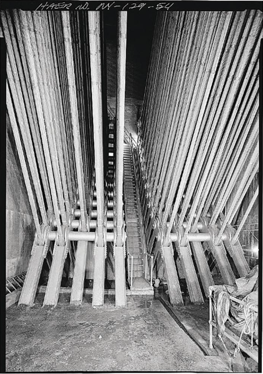
On the New York side, a gigantic structure, weighing 350,000 tons, required 110,000 cubic yards of concrete to anchor the bridge. Each main cable, of 26,474 galvanized five-millimeter diameter wires, splays into 61 strands of 434 wires connecting to eye-bar anchor chains and girders embedded in concrete to a 113-foot depth.
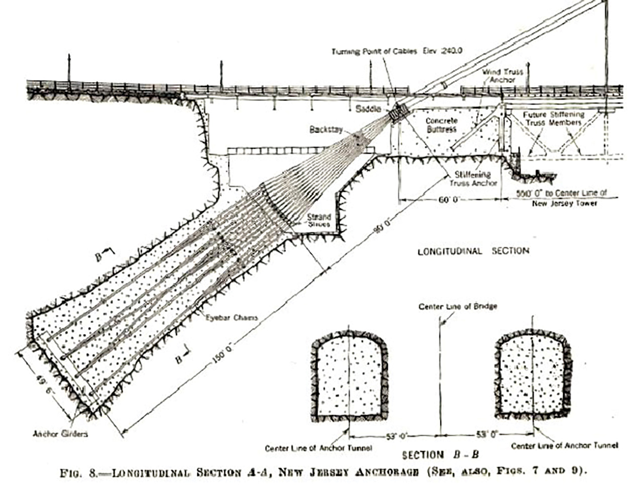
In New Jersey, tunnels were blasted into the trap-rock Palisades cliff to about a 150-foot depth to anchor the cables, with voids filled with reinforced concrete. Ammann, while working for bridge engineer Ralph Modjeski in 1905, acquired expertise in developing reinforced concrete technology, unlike many of his contemporaries.
Towers
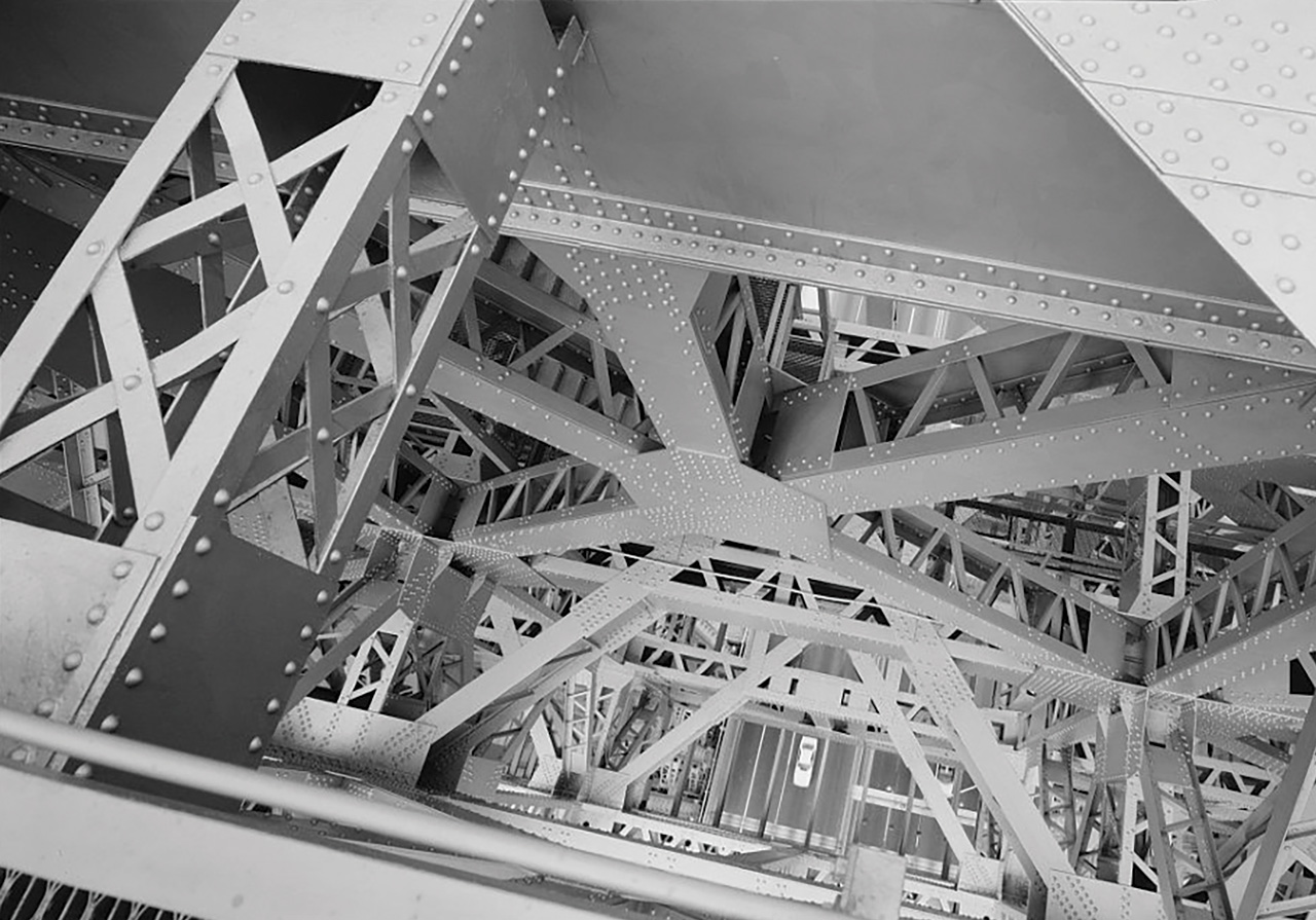
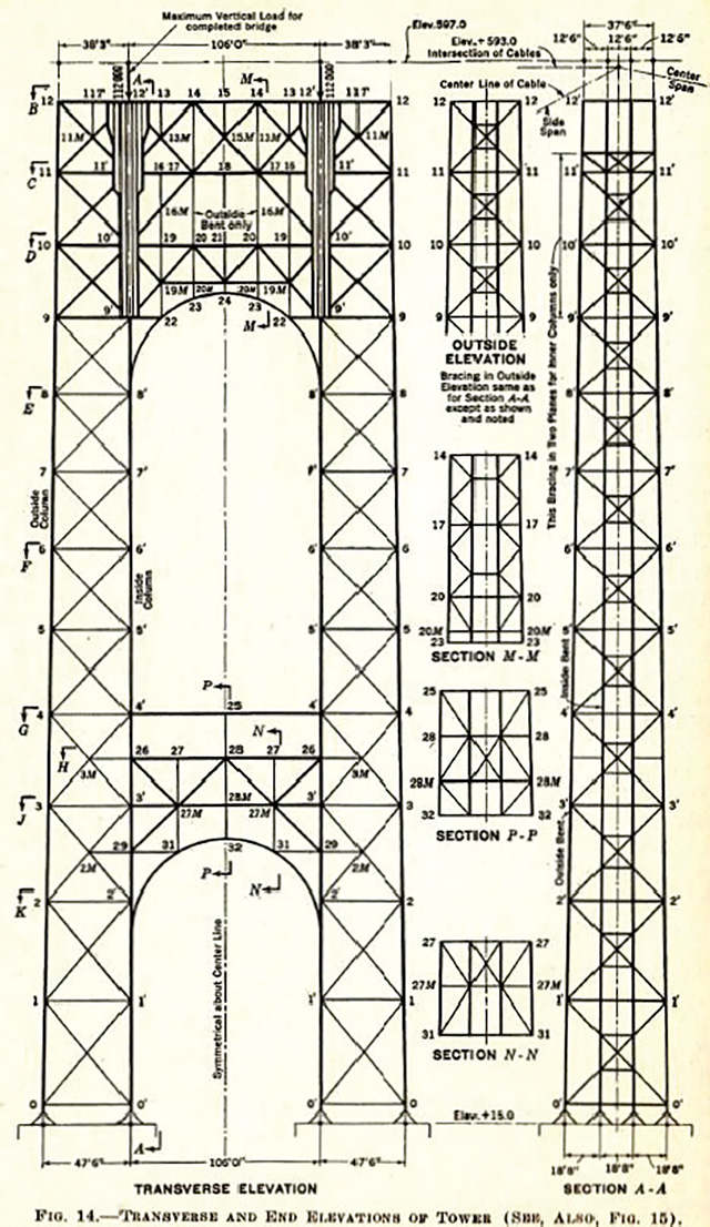
Leon S. Moisseiff (1872-1943), Advisor of Engineering Design for the project at the PNYA, designed each tower as four steel rigidly connected bents forming space frames, ascending to their great heights above MHW. The inner columns are vertical while the outer columns are battered 3/16 inch to the tower top. The enormous tower dimensions at the deck are 75 by 215 feet and taper to about 50 by 180 feet at the top. The chemical composition of the heavy 41,100-ton structural steel skeleton towers is 23,600 tons silicon steel and 17,500 tons carbon steel. The silicon alloy improves yield strength, elastic limit and fatigue strength.
The inner columns take the entire superstructure load, which is distributed via the diagonal truss members to the outer columns of the space frame. This load increases to a maximum at the deck and follows the load path to the ground.
The assumed future vehicular load of 45,500 load of pounds per linear foot for the planned 1960s lower level – conceived in Ammann’s original design –was included in Moisseiff’s original design calculations as well; at the same time, Moisseiff strengthened the connections for capacity to include the intended masonry covering.
Not completely trusting the new Deflection Method, Moisseiff performed stress-strain tests on a large model during different stages of construction on the indeterminate towers under various loadings to confirm the mathematical analyses. The main tower members were tested to failure in the model. As Navier had applied his own new simple formulas for forces in the elastic range to studies he had made on a structure, Moisseiff also carefully measured the physical behavior to compare with his calculations. A large on-site laboratory continuously tested all materials going into the bridge.
Steel Cables
The steel galvanized wire (maximum 0.85% carbon, E=28 x 106) with an ultimate strength of 230,000 psi) was three times stronger than any wire previously used. The thirty-six-inch diameter parallel-wire main cables each contained 26,474 wires, with a total wire weight of 28,300 tons, and an average of 21 percent air voids, compressed. Parallel wire can be compressed 40 percent more than twisted wire. Tensile strength for wire for the project tested at 82,000 psi, ten percent higher than previously manufactured.
Wires of cold-drawn galvanized steel were placed in position on the bridge, assembled, compressed, wrapped, and sealed with lead wool. Then, the resulting cables were covered in thick red lead paste and painted with two coats of aluminum in the traditional method of the nineteenth to early twentieth century suspension bridge cable making. However, by the 1920s the larger open-hearth steel billets and improved wire drawing technologies permitted the manufacture of greater wire lengths, quality, and dimensional consistency.
J.A. Roebling & Co manufactured the wire and, after wire drawing, experimented with stretching the wires in their plant yard. They thereby studied and furthered the technology of pre-tensioning, which advanced the idea of wire tendons for pre-stressing concrete, employed for example in 1950s highway concrete bridge construction.
Engineers of the era, including Ammann, did not fully grasp theoretical aeronautics. The great dead load of the original superstructure restrained the loaded cable-deformation adequately, itself stiffening the bridge until the 1960s lower deck construction. The original structure allowed for deflections of five feet laterally and ten feet vertically at the center of the main span, under live load and high temperature. [Walking the bridge deck in 35 mile per hour winds at 45 degrees on a partly cloudy spring 2022 day, the author noted marked vibration, vertical undulations and perceptible lateral motion.]
Post-Construction (Ongoing)
The bridge was still unfinished in its 1931 opening. Although wind diagonals were not originally planned for the lower deck designs of the 1920s, the added $182 million-dollar lower deck project in the 1960s included wind diagonals in plane with the bottom chord, similar to the top deck underfloor lateral system. The lower deck addition required adjusting the tower tops several inches shore-ward to resist the forces of the added deck weight and to reduce the top eccentricity of the cable saddles: The saddles originally were not aligned to the tower center lines, creating a slight eccentricity of load which needed to be corrected.
The PNYA developed a clandestine proprietary in-house prototype “digital computer” program for the lower deck analysis and computation, run on the 1950s-era refrigerator-sized computers. This technology saved personnel many thousands of calculating hours, and foretold the current digital age.
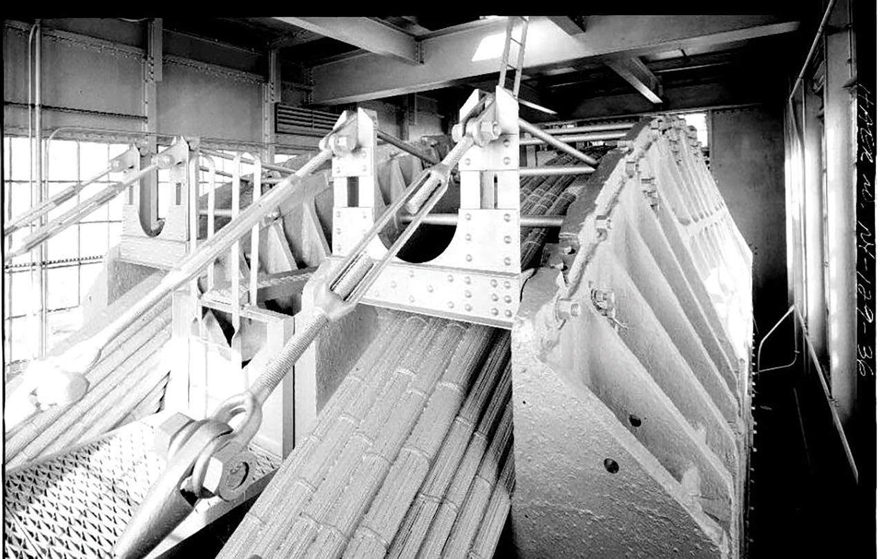
Inspections in 1997 revealed corrosion due to moisture of 440 wires of cold-drawn galvanized steel in three of sixty-one strands in Cable B at the New York anchorage. An innovative tie-back and clamp mechanism was employed by the New York office of the PANYNJ to restrain each strand’s loading of 400 tons while maintaining equilibrium of the element so that the new wires could be installed. The entire procedure was monitored by strain gauges and displacement transducers.
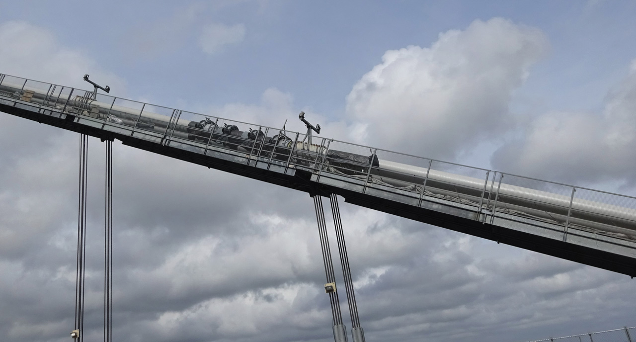
Ongoing rehabilitation includes upper deck finger expansion joint repairs, deck panel replacements at the towers, and main span paving. Work on the lower deck involves structural steel rehabilitation at the underfloor, lead paint removal and repainting, and replacement of maintenance platforms. The anchorage cable rehabilitation is complete, along with most suspender rope replacement. A significant part of ongoing work involves rehabilitation of the main cables, including installation of a dehumidification system. Sensors scattered throughout the cable air voids will also detect and monitor vibrations, displacements, moisture, temperature, location, and sound, the information from which will be collected into a structural health monitoring (SHM) database, allowing immediate inspection, evaluation, and repair. Temperature and corrosion are linearly related, and sound data can pinpoint areas of broken corroded wires.
This “Unfinished” bridge – opening in 1931 without its originally planned masonry encasement of the towers or its intended observation deck and restaurant at the tower tops – stands as it is today as the result of the automobile, a 1929 economic crash, advancements in the strength of materials, and the force of public opinion as to whether an exposed-steel skeleton qualified as an acceptable aesthetic.■
References
Alampalli, S. Correlation between Bridge Vibration and Bridge Deck Cracking; A Qualitative Study. Albany, N. Y.: Transportation Research and Development Bureau, New York State Department of Transportation. 2001.
Ammann, Othmar. “George Washington Bridge: General Conception and Development of Design.”Transactions of the American Society of Civil Engineers. 97: 1818, 1-65. 1933.
Ammann, Othmar. “The Hudson River at New York between Fort Washington and Fort Lee.” Proceedings of the Connecticut Society of Civil Engineers. v. 47, 47-74. 1928.
Ammann, Othmar. “The Problem of Bridging the Hudson River at New York with Particular Reference to the Proposed Bridge between Fort Washington and Fort Lee.” Proceedings of the Connecticut Society of Civil Engineers. v. 40, 5-26. 1924.
Baker, Herbert J. “George Washington Bridge: Materials and Fabrication of Steel Structure.” Transactions of the American Society of Civil Engineers. 97: 1824, 330-377. 1933.
Bowden, E. W. and H. R. Seely. “George Washington Bridge: Construction of the Steel Superstructure.” Transactions of the American Society of Civil Engineers. 97: 1823, 242-329. 1933.
Case, Montgomery B. “George Washington Bridge: Construction of Substructure.” Transactions of the American Society of Civil Engineers. 97: 1822, 206-241. 1933.
Condit, Carl W. American Building Art: Twentieth Century. New York: Oxford University Press. 1961.
Dana, Allston et. al. “George Washington Bridge: Design of Superstructure.” Transactions of the American Society of Civil Engineers. 97: 1820, 66-96. 1933.
Delatte, Norbert T., Jr. Beyond Failure; Forensic Case Studies for Civil Engineers. Reston, Va.: American Society of Civil Engineers. 2009.
Doig, Jameson W. Metropolitan Transportation Politics and the New York Region. New York: Columbia University Press. 1966.
Elliot, Cecil D. Technics & Architecture: Development of Materials and Systems for Buildings. Cambridge, MA.: MIT Press. 1992.
Englot, Joseph M. and Peter L. Rinaldi. “George Washington Bridge Cable Anchorage Restoration.” Proceedings of Structural Congress. XV, 1489-1495. April, 1997.
Evans, J. C. “George Washington Bridge: Approaches and Highway Connections.” Transactions of the American Society of Civil Engineers. 97: 1825, 378-416. 1933.
Fichen, J. Building Construction before Mechanization. Cambridge, MA.: MIT Press. 1986.
Freiman, Fran L. Failed Technology & True Stories of Technological Disasters. v. 1. Detroit: UXL Press. 1995.
Gould, Irvine. P. “Design Features of the George Washington Bridge Lower Level.” Transactions of the American Society of Civil Engineers. 125: 1: 1022-1032. 1960.
Hildenbrand, Wilhelm. Cable Making for Suspension Bridges: with Special Reference to the Cables of the East River Bridge. New York: van Nostrand. 1877.
Kaminetzky, Dov. Design Construction Failures; Lessons from Forensic Investigations. New York: McGraw-Hill. 1991.
Kunz, George F. Geology of the Hudson River and its Relation to Bridges and Tunnels. Albany, N. Y.: J. B Lyon Company. 1913.
Lindenthal, Gustav. “A Rational Form of Stiffened Suspension Bridges.” Transactions of the American Society of Civil Engineers. 55: 1-62. 1905. Accessed 3.11.2020. https://hdl.handle.net/2027/mdp.29015021288645
Moisseiff, Leon. “George Washington Bridge: Design of the Towers.” Transactions of the American Society of Civil Engineers. 97: 1821, 164-205. 1933.
Moisseiff, Leon. “Theory and Formulas of a Three-Span Bridge with Braced Cables.” Transactions of the American Society of Civil Engineers. 55: 94-122. 1905. Accessed 3.11.2020. https://hdl.handle.net/2027/mdp.29015021288645
Morison, George. “Suspension Bridges; a Study.” With Discussion. Transactions of the American Society of Civil Engineers. 35: 359-471. 1896. Accessed 3.11.2020. https://hdl.handle.net/2027/uva.x002223296
Navier, M. Rapport a M. Becquey; Memoire sur les Ponts Suspendus. Paris: Imprimierie Royale. 1823. v.1, Texte; v.2, Planches.
Petrosky, Henry. Design Paradigms. New York: Cambridge University Press. 1994.
Port Authority of New York and New Jersey. Accessed 8.29.2022. https://www.panynj.gov/bridges-tunnels/en/traffic—volume-information—b.t.html
Port of New York Authority. Annual Report. Albany, N. Y.: J. B. Lyon Company. 1924-1929. Accessed 4.9.2022. https://hdl.handle.net/2027/umn.31951002249341
Port of New York Authority. Progress Reports on the Hudson River at New York, between Fort Washington and Fort Lee. Albany, N. Y.: J. B. Lyon Co., Printers, v.1-4. 1928-30.
Port of New York Authority. Tentative Report of Bridge Engineer on Hudson River Bridge at New York between Fort Washington and Fort Lee, February 25, 1926. New York, New York: Pantick Press, Inc., Printers. 1926. Accessed 3.2020. https://hdl/handle/net/2027/mdp.39015021228419
Rastorfer, Darl. Six Bridges: the Legacy of Othmar H. Ammann. New Haven, CT: Yale University Press. 2000.
Sayenga, Donald. “Contextual Essay on Wire Bridges, John A. Roebling & Sons Co.” www.loc.gov, HAER (Historic American Engineering Record) No. NJ-132, 11-Tret, 36.
Special Committee of the Board of Directors. “Failure of the Tacoma Narrows Bridge.” Proceedings of the American Society of Civil Engineers. 64: 10, 1555-1586. December, 1943.