
Fall from height represents one of the highest occupational hazards in general industry and at construction sites. Personal fall protection equipment is frequently used to abate this hazard as part of a fall arrest or travel restraint system, where the point of anchorage is a critically functional part of this operation. However, what is the role of the structural engineer in the overall design of fall safety systems? Proper understanding of structural implications and other design aspects is vital to the individuals who trust their livelihood each time they engage to a fall protection anchorage system.
Background and Design Basics
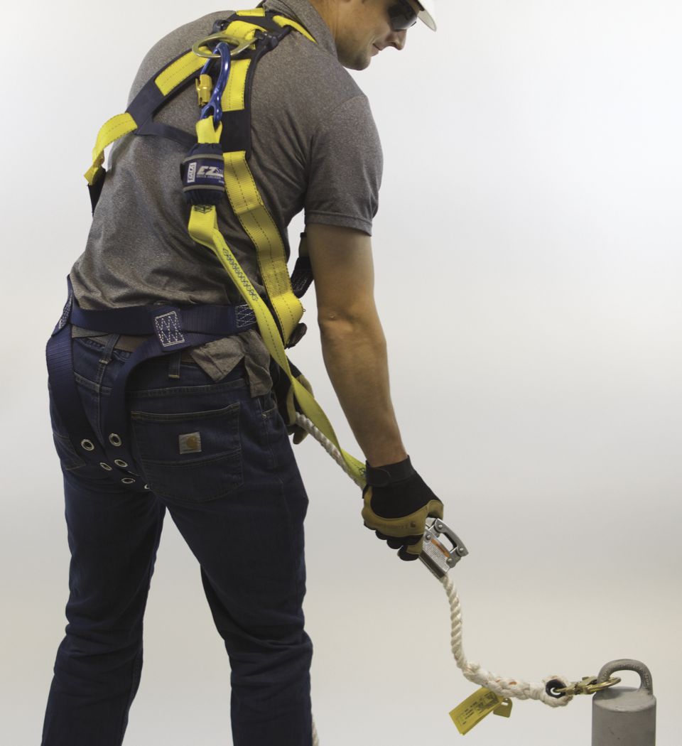
An anchorage, also commonly referenced as an anchor point, is defined by the Occupational Safety & Health Administration (OSHA) as a secure point of attachment for equipment such as lifelines, lanyards, or deceleration devices. An anchorage is part of a complete personal fall arrest system along with a safety harness and a connecting device. Safety harnesses are responsible for distributing dynamic fall arrest forces to body parts that are most capable of experiencing the load without injury or positioning the user to prevent such a fall. Certain harnesses are also equipped with features to facilitate rescue in the event of a fall. The connecting device joins the safety harness to the anchor, typically furnished as an energy-absorbing lanyard or self-retracting device, sometimes in tandem with rope grabs or other accessories. Various connecting devices are available with lengths, materials, and other characteristics to suit the specific application. These devices are not “one size fits all,” and proper selection is integral to the overall system design.
If falls are arrested dynamically, how can the applied load for static analysis of an anchor point be determined? There are two basic products available in the fall protection industry to meet requirements by OSHA to limit the fall arrest forces on a user: personal energy absorbers and clutching self retracting devices (SRD). Each is designed with a rated Maximum and Average Arresting Force determined by manufacturer testing. In the event of a fall, once the tension in the lanyard or SRD approaches these values, the absorption mechanism in each elongates as energy is absorbed. Therefore, the maximum force experienced by the user during this process is generally equivalent to the maximum force applied to the supporting anchorage.
Fall protection anchorage system design must consider factors such as anchorage system layout, structural adequacy of the anchorage and supporting structure, selection of a compatible safety harness and connecting device, trained technicians to install and inspect, and trained personnel to supervise the use of the system by designated authorized users. Although the structural capacity of the anchor is a major consideration, a comprehensive design requires an evaluation of the overall system. Typical anchor design loads are reliable only to the extent that the system is used correctly, which is highly contingent on the proper placement of the anchorage and the proper selection of the connecting device. Spatial considerations are critical to reducing or eliminating total fall distance. Preferably, the anchorage location is such that the user, once tied off with a properly sized connecting device, would be restrained from reaching an identified hazard. If travel restraint cannot be practically afforded, other spatial considerations must be made to reduce the total fall distance to tolerable limits and ensure any swing fall distance does not present additional hazards in a fall arrest event. Analysis of required fall clearance considers the free fall distance and deceleration distance required to bring the kinetic energy developed by the falling user to zero. Total required fall clearance includes factors such as maximum anchorage system deflection, harness stretch, and an associated clearance factor. The fall protection engineer then checks this cumulative value against the available clearance to ensure adequate clearance to arrest the user’s fall.
Applications
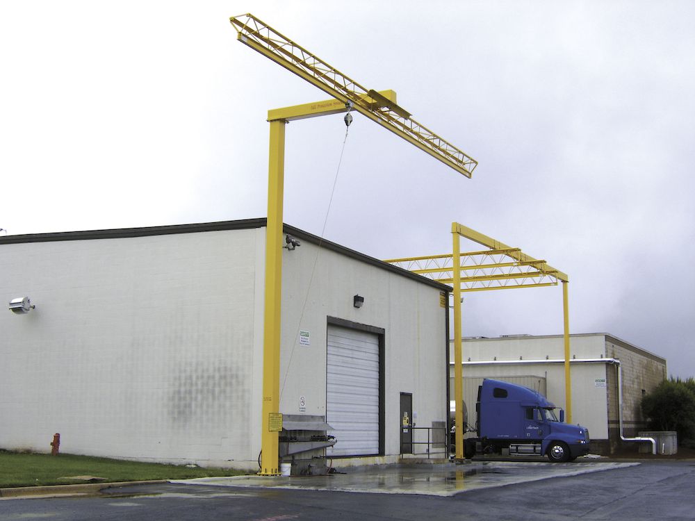
Fall protection anchorages are used in a wide array of applications. Where falls cannot be guarded or otherwise practically eliminated, anchorages serve as the point of structural connection to support work in travel restraint or fall arrest. Typical applications range from maintenance of rooftop areas to manufacturing equipment, transportation, mining, telecommunication, and wind energy. Depending on the application, duration, and frequency of the task, anchorages may be installed temporarily or permanently. Anchorage systems may be designed as a single point connection with an effective working radius, linear systems to provide access along a continuous edge, or to support linear travel along a traveling rail. Anchorages are also used to support suspended access for exterior building maintenance, façade construction, inspections, and similar activities. Anchorages that support suspended access equipment lines should be separate and independent from personnel safety lines. Vertical tower or ladder climbing fall arrest systems are subject to application-specific standards such as the ANSI/ASSE Z359.16 Safety Requirements for Climbing Ladder Fall Arrest Systems.
Responsible Parties
According to the OSHA Multi-Employer Citation Policy (MECP), more than one employer may be citable for a hazardous condition that violates an OSHA standard. Any employer who has a role in creating, exposing, correcting, or controlling a hazardous condition has an obligation with respect to OSHA requirements. As such, responsible parties commonly include general contractors, subcontractors, and building owners but may also include design professionals and other vendors. The responsibility for identifying and eliminating fall hazards is a duty shared by multiple parties, each integrated to serve in a more specific role.
The employer is first responsible for ensuring the workplace has been properly abated of fall hazards. According to OSHA 1910.132(d)(1), “The employer shall assess the workplace to determine if hazards are present, or likely to be present, which necessitate the user of personal protective equipment….” The employer is also responsible for verifying that this hazard assessment has been performed following OSHA 1910.132(d)(2). This requirement typically results in an arrangement where the employer designates a responsible party to perform the hazard assessment. That hazard assessment becomes the basis for designing and implementing the system designated within those recommendations. The scope of these findings may vary significantly, and the employer is best served by requiring an assessment that complies with ANSI/ASSE Z359.2, Minimum Requirements for a Comprehensive Managed Fall Protection Program, which includes applicable guidelines. For example, the design of new facilities is subject to ANSI/ASSE Z359.2 5.3.2, which stipulates, “When planning and designing new buildings or facilities, architects, planners, engineers, and designers, including the owner and managers of such facility, shall provide a safe design and shall protect all authorized persons who will be exposed to fall hazards during performance of their work including maintenance and normal workplace operation.”
Upon completion and review of the hazard assessment, the employer may choose to engage other responsible parties to direct the final design, installation, and eventual operation of the systems designated. These parties are often engaged through a bid or vetting process based on experience qualifications and a stated scope of work subject to performance qualifications. Ultimately, the employer and/or owner should ensure that each contracted party is qualified to complete the scope for which they were contracted and to ensure no gaps in scope. The party responsible for hazard assessment is often engaged to craft a specification to provide this level of assurance. OSHA 1910.140 defines a qualified person as “a person who, by possession of a recognized degree, certificate, or professional standing, or who by extensive knowledge, training, and experience has successfully demonstrated the ability to solve or resolve problems relating to the subject matter, the work, or the project.” Although not specifically covered within this review, ongoing inspection, maintenance, and training are critical to the system’s continuous compliant use and ensuring that the initial investment reaches full life expectancy.

Structural Provisions and Applicable Standards
Anchorage strength is subject to the structural design of the anchor itself, the connection to its supporting structure, and the capacity of the supporting structure to resist the anchor live loads, all relative to any direction that a load may be applied. Often, proper transfer of anchor live loads requires bracing or supplemental support. Additionally, the supporting structure should be designed with adequate bearing space to allow for proper connections. The fall protection engineer is typically responsible for designing the anchorage to include a connection to the building structure. When a separate Structural Engineer of Record is integrated into the design team, the structural analysis below the point of connection is typically the responsibility of this party. In this case, the fall protection engineer should clearly indicate the applied loads on submittal drawings and calculations to ensure a coordinated effort.
While computations for design strength and allowable stress remain consistent with commonly used structural engineering codes, the required design loads and safety factors may seem less trivial when exploring the requirements of OSHA, ANSI/ASSE Z359, IBC, and other state and local building codes.
The most comprehensive resource to determine applied loads and load combinations is ANSI/ASSE Z359.6, Specification and Design Requirements for Active Fall Protection Systems. Design loads to consider for analysis include environmental loads and occupancy loads as determined by ASCE/SEI 7, Minimum Design Loads and Associated Criteria for Buildings and Other Structures, in addition to dead loads including self-weight of the structure, active loads applied by a user in a fall arrest scenario, and equipment loads from any devices attached to the anchorage connector such as a hoist for suspended façade maintenance. Attention should also be given to self-straining loads, particularly for larger structures with increased spans and components on independent foundations where creep, thermal effects, and moisture changes should be considered.
Each load described above should be defined and applied to load combinations established in ANSI/ASSE Z359.6, Specifications and Design Requirements for Active Fall Protection Systems, to determine the required strength of all structural components in the fall protection system.
When all the design parameters are considered, OSHA standard 1910.140 states, “Anchorages […] must be […] Capable of supporting at least 5,000 pounds (22.2 kN) for each employee attached; or designed, installed, and used, under the supervision of qualified person, as part of a complete personal fall protection system that maintains a safety factor of at least two” [1910.140(c), (1910.140(c)(13)(i), 1910.140(c)(13)(ii)]. ANSI/ASSE Z359 is a series of national consensus standards; therefore, designing to the requirements defined above is an acceptable means to design a complete fall arrest system. Furthermore, ANSI/ASSE Z359.6 Appendix A.5 declares its intent and methodology to ensure the resulting designs of a complete fall arrest system, according to its guidance, achieve a safety factor of at least 2. This Appendix also draws alignment as to how their guidance relates to load factors required by the International Building Code (IBC).
The fall protection engineer may also designate proof testing before final certification. In the case of suspended access anchorages, testing is a stated OSHA requirement and provides additional assurance of proper anchorage design, production, and installation.
Examples
As a case study for exterior fall protection systems designed to support fall arrest, ANSI/ASSE Z359.6 Section 6.1.2 considers the fall arrest or travel restraint load of the user as “A.” This load typically correlates to the maximum arrest force (MAF) of the user’s energy-absorbing lifeline and should be selected by the qualified fall protection engineer. The active load is generally vertical due to gravity but should consider angulation due to the geometry of the protected surface relative to the elevation of the anchorage connection. The fall protection engineer will also place user weight limitations, including tools, based on the selected lifeline. The total design fall load on the system also considers the number of users and an associated lumping factor. ANSI Z359.6 Section 6 indicates applicable load factors using allowable stress design or strength design and load combinations for accounting for environmental effects. It is important to consider the site-specific load effects and the maximum allowable conditions for safe use, such as maximum wind speed. Environmental parameters should be coordinated between the owner and fall protection engineer based on expected use concurrent to those conditions. For example, use of the anchorage system may be restricted by specified wind or snow loads. Environmental loads may govern for larger-scale exterior systems, but these effects are negligible for smaller-scale anchorage systems such as roof-mounted anchorage posts.
Roof structure mounted anchorages are often integrated into building design for suspended access or general fall protection. This most frequent application includes a post that extends through the roofing system and makes a connection with the structure below. Connection types vary but most commonly include a welded post, baseplate with bolts to structural steel members, or embedded plates with headed studs. The International Building Code (IBC) 2018 1607.10.4 indicates a minimum design load of 3,100 pounds for fall arrest and lifeline anchorages “…for each attached lifeline, in every direction that a fall arrest load can be applied.” The IBC commentary clarifies their intent that this is an unfactored design load which, given a live load factor of 1.6, results in an LRFD ultimate load of 4,960 pounds which is within an acceptable margin of error compared to OSHA’s 5,000-pound requirement. It is important to note that an anticipated direction of this applied load is not always reliable, as the structural designer cannot always predict the orientation of the rigging over the life of the building.
Conclusion
Safe design of a fall protection system requires the integration of a team, each member contributing to their respective area of expertise. The structural designer should prompt the design team to ensure proper coordination if the design process does not reflect a properly concerted effort. The omission of key team members may otherwise result in scope gaps that are costly to reconcile after implementation or go unrecognized. Working in concert, an effective design team provides the level of assurance that a system user can trust as a life safety connection.