
This article provides background on the seismic design of cross-laminated timber (CLT) shear wall systems following ASCE 7-22 Minimum Design Loads and Associated Criteria for Buildings and Other Structures and ANSI/AWC Special Design Provisions for Wind and Seismic (SDPWS) 2021 Edition. The SDPWS is referenced in the 2021 International Building Code (IBC), and both SDPWS and ASCE 7-22 will be referenced in the 2024 IBC.
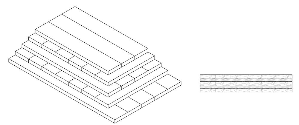
CLT is a prefabricated engineered wood product made of at least three orthogonal layers of graded sawn lumber or structural composite lumber that are laminated by gluing with structural adhesives. A typical CLT panel configuration is shown in Figure 1. Testing, qualification, and quality assurance requirements for CLT are established by ANSI/APA PRG320 Performance-Rated Cross-Laminated Timber. CLT was first recognized in U.S. model codes in the 2015 IBC through the addition of a reference to the PRG 320 product standard and with the inclusion of requirements for the design of CLT in the 2015 edition of ANSI/AWC National Design Specification for Wood Construction (NDS).
CLT Shear Wall Design Requirements
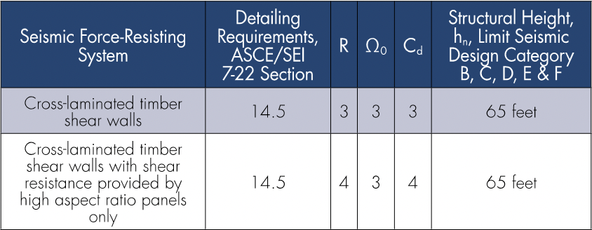
The two defined CLT shear wall system types in SDPWS are: (a) CLT shear wall system and (b) CLT shear wall system with shear resistance provided by high aspect ratio panels only. Both have seismic design factors (i.e., R, Ω0, Cd) provided in ASCE 7-22 Table 12.2-1. Seismic performance factors and structural height limits appearing in ASCE 7-22 are summarized in Table 1.
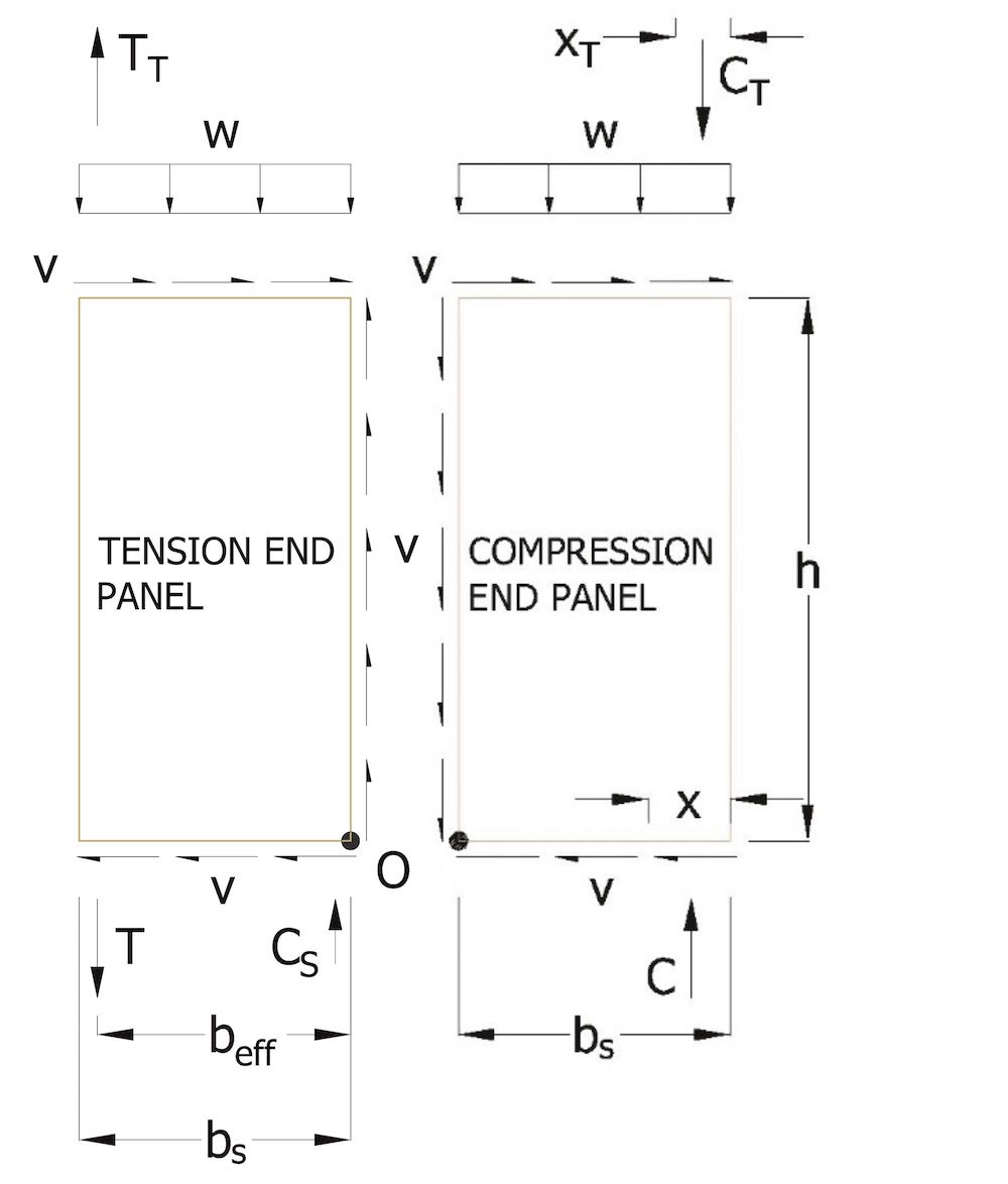
Individual CLT panels of CLT shear walls are expected to exhibit rocking, as shown in Figure 2, with the strength of the system controlled by nailed connections. Typical CLT shear wall configurations with the corresponding components are shown in Figure 3. Prescribed nailed connectors are shown at the bottoms and tops of panels and at adjoining vertical panel edges. For multi-panel configurations, free-body diagrams for the tension end panel and compression end panels are shown in Figure 4.
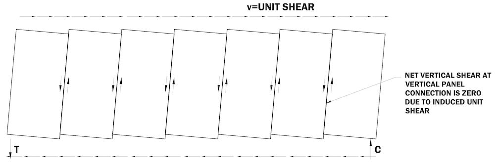

To ensure rocking behavior, as shown in Figure 2, and development of the nailed connection strength, design requirements include: (1) use of CLT panels of prescribed aspect ratios; (2) use of prescribed nailed connectors at bottoms of panels, tops of panels, and adjoining vertical edge(s) of multi-panel shear walls; (3) strength requirements for overturning tension devices (e.g., hold-downs); and (4) compression zone length requirements. Design requirements also include equations for calculating nominal unit shear capacity provided by the prescribed nailed connectors and for calculating the CLT shear wall deflection. The structural design of the CLT panels for resistance to tension, compression, bending, and shear, as well as the design of connections to CLT panels, is required to be in accordance with the NDS. Requirements for the design of CLT diaphragms are also provided in SDPWS.
SDPWS and SDPWS Commentary include additional information to support the new requirements:
- For the CLT shear wall (R=3) system, different wall lines can have CLT shear walls composed of CLT panels of different aspect ratios ranging from 2:1 to 4:1.
- For the CLT shear wall system with shear resistance provided by high aspect ratio panels only (R=4), different wall lines must have CLT shear walls composed of CLT panels with an aspect ratio of 4:1.
- Connectors need not be aligned from story above to story below.
- Connectors can be placed on one side of the wall only or on opposite sides.
- The top- and bottom-of-wall connectors include a prescribed lag screw option in the horizontal leg.
- Any change in connectors as prescribed in SDPWS Section B.3.2 and Section B.3.3 would be subject to an alternative method evaluation (see SDPWS Commentary C-B.3).
Additional Resources for Seismic Requirements
Background information on the development of the CLT shear wall system is available in General Technical Report FPL-GTR-281 Determination of Seismic Performance Factors for Cross-Laminated Timber Shear Walls Based on the FEMA P695 Methodology. The report includes testing, modeling, and archetypes that led to the development of seismic design coefficients for the CLT shear wall system.
The NEHRP Recommended Seismic Provisions for New Buildings and Other Structures, Volume I: Part 1 Provisions and Part 2 Commentary, 2020 Edition, FEMA P-2082-1 includes design requirements for CLT shear walls. As a predecessor to requirements in ASCE 7-22 and SDPWS, the NEHRP requirements are similar but not identical to those appearing in SDPWS.
Example Application of Design Requirements
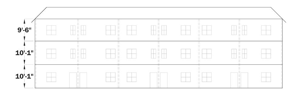
The 2020 NEHRP Recommended Seismic Provisions: Design Examples, Training Materials, and Design Flow Charts, FEMA P-2192, contain design examples based on the 2020 NEHRP Provisions. FEMA P-2192 includes an approximate 25-page example of the CLT shear wall system following the requirements of ASCE 7-22 and SDPWS. The example features the seismic design of cross-laminated timber shear walls used in a three-story, six-unit townhouse cross-laminated timber building of platform construction shown in Figure 5. The example includes:
- A check of CLT shear wall shear strength, which is governed by the strength of connectors having significantly less in-plane shear strength than the CLT panel itself. Table 6-5 of the design example (FEMA P-2192-V1) summarizes the number of top-of-wall and bottom-of-wall connectors, adjoining panel edge connectors, and associated LRFD unit shear capacities following SDPWS Section B.5 and Section 4.1.4. While wall panel thickness remains unchanged over the three-story height of the structure, the number of connectors per story increases when progressing from top to bottom story to meet increasing design story shears at lower stories.
- A check of CLT shear wall hold-down size and compression zone length for overturning, which shows the use of conventional hold-downs for tension and that the compression zone is confined to the outermost panel. Table 6-6 (FEMA P-2192-V1) includes solutions for tension force, T, for hold-down strength requirements. The dead load used to offset overturning induced uplift is limited to that portion supported by or directly above the individual CLT panel (SDPWS Section B.2), consistent with assumed individual panel rocking behavior. Countering dead load is not based on the assumption that the wall overturns as a rigid monolith. The example illustrates that overturning-induced hold-down forces and compression zone forces increase when progressing from top to bottom story and are tied to the shear strength of the provided connectors. Greater efficiency in design for in-plane shear, such that the provided in-plane unit shear capacity by connectors is minimized, leads to reductions in the required size of hold-downs and compression zone.
- A check of CLT shear wall deflection, which shows seismic story drift is small relative to allowable story drift limits of ASCE 7-22. CLT shear wall deflection is calculated using SDPWS Equation B-1 that incorporates individual components of deflection: individual wall panel bending and shear, sliding and panel rotation due to fastener slip, and rigid body overturning. For the example wall designs, which utilize panels with a height-to-length ratio of 2, the primary contributor to deflection is fastener slip which remains similar across stories due to a similarity in load per fastener at each story level. This similarity results from an increased number of fasteners to match increased design demand at lower stories.
The FEMA P-2192 CLT design example does not address all system requirements implemented for CLT shear walls in 2021 SDPWS, including but not limited to requirements for CLT diaphragms and requirements for deformation compatibility of CLT walls that are not designated as part of the seismic force-resisting system. The example does not address the use of CLT as part of a hybrid structural system where CLT panels are used in floors for both gravity load-carrying and diaphragm function while other structural systems are used as the vertical elements of the seismic force-resisting system such as wood-frame wood structural panel shear walls, concrete shear walls or moment frames, or steel braced frames or moment frames.
Conclusion
Design requirements for CLT shear walls and diaphragms are included in the 2021 SDPWS. The 2021 SDPWS is referenced in 2021 IBC Section 2305 for lateral design and construction. Recognition of CLT shear wall system seismic design is incorporated in ASCE 7-22, which will be referenced in the 2024 IBC.
References
ASCE/SEI 7-22 Minimum Design Loads and Associated Criteria for Buildings and Other Structures. American Society of Civil Engineers. Reston, VA. 2022.
Special Design Provisions for Wind and Seismic (SDPWS), SDPWS-21. American Wood Council. Leesburg, VA. 2020.
National Design Specification (NDS) for Wood Construction, NDS-18, American Wood Council, Leesburg, VA. 2017.
Standard for Performance-Rated Cross-Laminated Timber, ANSI/APA PRG 320-19, APA-The Engineered Wood Association. Tacoma, WA. 2020.
NEHRP Recommended Seismic Provisions for New Buildings and Other Structures, Volume I: Part 1 Provisions and Part 2 Commentary, FEMA P-2082-1, prepared by the Building Seismic Safety Council of the National Institute of Buildings Sciences for Federal Emergency Management Agency. 2020.
NEHRP Recommended Seismic Provisions: Design Examples, Training Materials, and Design Flow Charts, FEMA P-2192, prepared by Building Seismic Safety Council of the National Institute of Buildings Sciences for Federal Emergency Management Agency. 2020.
van de Lindt, J., Amini, M. O., Rammer, D., Line, P., Pei, S., and Popovski, M. “Determination of Seismic Performance Factors for Cross-Laminated Timber Shear Walls Based on the FEMA P695 Methodology.” General Technical Report FPL-GTR-281, Madison, WI: U.S. Department of Agriculture, Forest Service, Forest Products Laboratory. 2022.