
CFS Load-Bearing Prefabricated Panels
Off-site construction is the future of the building industry. It aims to speed up on-site construction schedules, address skilled worker shortages, and achieve better pre-coordination. Given their lightweight nature, cold-formed steel (CFS) framing projects are uniquely situated to use prefabricated panels. The panels can be complete with all the framing, sheathing, and possibly finishes installed in the fabrication facility.
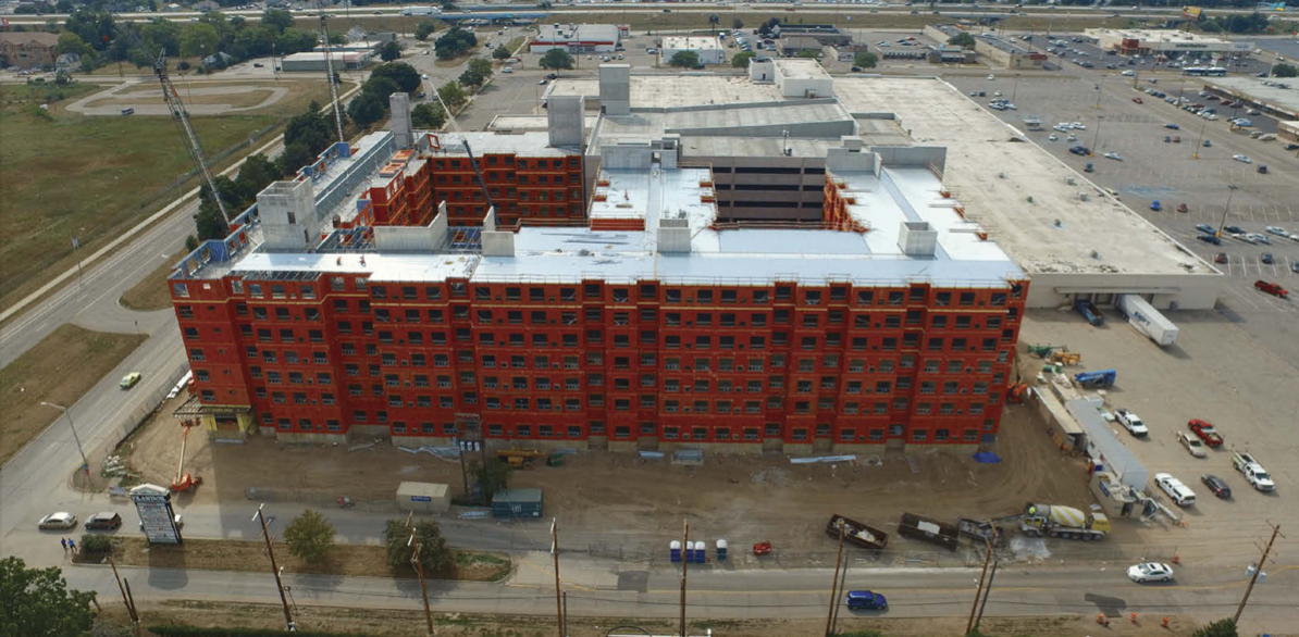
CFS framing is widely used as the primary structural system in mid-rise buildings. It brings the value of reduced building mass that directly affects the design of the building foundation and the design of the lateral force-resisting system to resist lateral forces. Projects that benefit from CFS framing include multi-family housing, assisted living, dorms, hotels, barracks, and mixed-use buildings (see Figure 1 for an example of a 9-story mixed-use building under construction).
This article presents the opportunity for off-site construction using prefabricated CFS panels in mid-rise load-bearing wall construction. The design methods, fabrication, and installation techniques for CFS panel sare discussed, as well as the coordination between CFS, MEP and other structural members.
Deciding to Use CFS Panels
Early in the project’s design phase, the project team, including the general contractor, the owner’s representative, the architect, and the engineer of record, typically explore the various structural systems to decide the best system for their project. Factors that affect their decision might include the size of the project (number of floors or total square foot area), the architectural layout, the construction schedule, job site constraints, budget, and consideration of any shortages of skilled field workers. CFS load-bearing panelization can reduce the construction schedule and address on-site skilled worker shortages and job site constraints; however, added shipping and crane costs should be considered in the analysis.
If the decision is made to use CFS prefabricated panels, it is advantageous to select the panel supplier early in the design process to ensure upfront coordination between the design details and the construction methods. An example of critical early communication is the location of anchorage embed plates in a podium slab. When parties communicate early, shear wall plates can be efficiently located and coordinated with the lateral force resisting system (LFRS) design. However, if this is an afterthought, resolving the forces from the LFRS can be quite complicated.
What Gets Panelized?
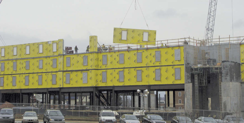
It is common to panelize the interior and exterior load-bearing walls in a CFS load-bearing building. The wall segments, historically called panels, are typically one story high and as wide as the panel can be handled in fabrication, transportation, and installation (Figure 2). When the floor and/or the roof design uses CFS framing, they can also be panelized. In some projects, even the non-load-bearing CFS walls are panelized.
Vertical Load Path
Designing panelized load-bearing CFS is similar to the design of field-built CFS framing. Regardless of the system, the normal vertical load path is maintained. Wind, snow, dead, and live loads are considered at the roof level. At the floor level, the various dead and live load conditions are considered. However, panelization can present unique design challenges. For example, during construction, the contractor may stack panels on finished floors before installation. This additional construction loading should be reviewed to ensure that it does not exceed the structural capacity of the framing in the area where stacking may occur. Another example is addressing the in-plane bracing forces generated within a wall panel from vertical loads. Depending on the selected panel width, each panel can have its own anchorage points, or the designer should address the transfer of bracing forces between panels.
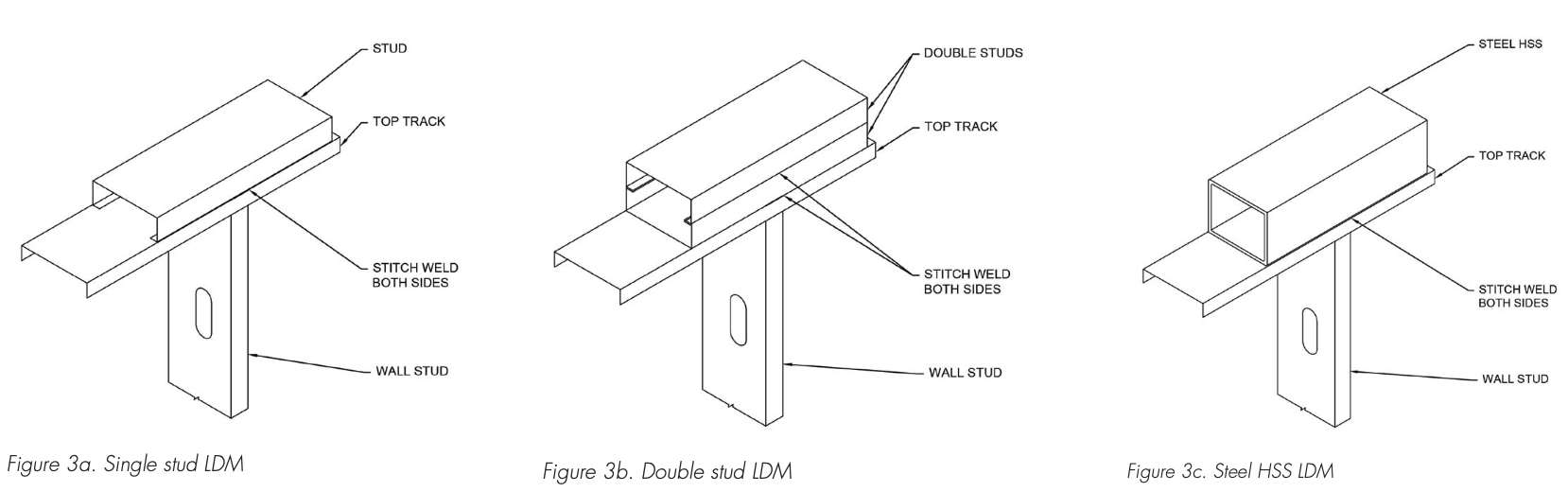
Panelized wall framing can be utilized with several different floor and roof systems. The differing systems may affect how the gravity (and lateral) loads are applied to the wall panels. When the floor framing members do not align with the wall framing members, a load distribution member (LDM) may be needed to distribute the gravity load to each wall stud. Some examples of LDMs contained within the floor system are a CFS floor with a ledger track or a concrete deck with a concrete LDM over the wall. Other systems may have the LDM contained within the wall panel. This can be achieved using a properly designed stud and track or an HSS member. These members are then included in the wall panel instead of the floor system (Figure 3).
Wall to Floor/Roof Connections
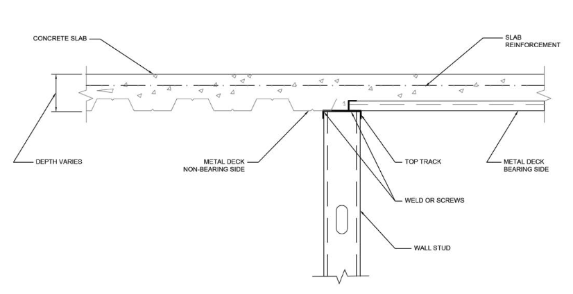
After installing the floor/roof panels or other floor/roof systems at each level, a discrete positive mechanical attachment should be executed between the floor/roof and the wall. This mechanical attachment can be in the form of screw fastening, power-actuated fasteners, or welds. In the case of ledger-framed floor panels to wall panels (Figure 4), each floor joist is secured to the ledger track utilizing a clip angle and screws, and then the ledger track is fastened with screws to the face of each wall stud. In the case of a concrete slab on steel deck (Figure 5), the deck is welded or screw-fastened to the top track of the wall panel.
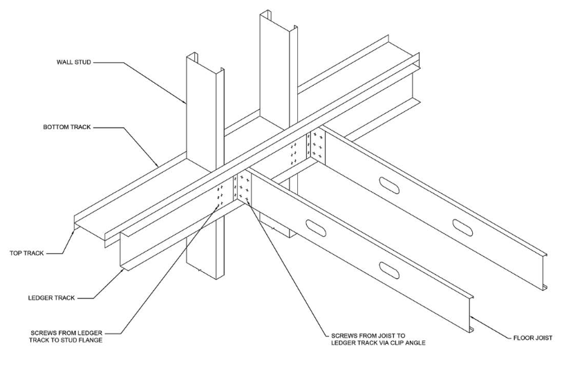
Figure 4. Attachment of Ledger-framed CFS floor panels to wall panels
Other Materials
There are instances where materials other than CFS framing may be included in a panelized wall. Structural steel is the most common; however, there may be instances where other materials, such as clips, hold-downs, or timber blocking, are included.
Structural steel has several uses in a wall panel and should be properly coordinated. HSS members lend themselves to uses within a CFS wall since the dimensions match typical framing, i.e., 4, 6, or 8 inches, etc. As noted above, an HSS member may be a good LDM solution. In addition, they can be useful when design loads exceed the capacity of typical CFS framing. This can occur when the number of shear walls is limited and the axial load demand at the lower levels is high. The same goes for posts when axial load accumulates over many floors or posts needed to support special point loads. It should be noted that Section 704.4.1 of the 2021 IBC allows structural steel members located entirely between the top and bottom tracks of CFS wall panels to have their fire-resistance ratings provided by the gypsum board layers on the wall.
Lateral Load Path
As with field-built CFS framing, panelized load-bearing CFS can be used with various lateral force resisting systems (LFRS). Some examples include CFS shear walls with wood sheathing or sheet steel, strap-braced CFS wall panels, steel brace frames, concrete shear walls, and masonry shear walls. However, it is important to note that ASCE 7, Minimum Design Loads and Associated Criteria for Buildings and Other Structures, specifies limitations on the heights of some lateral systems. For example, CFS shear walls and CFS strap braced walls are limited to 65 feet in height for Seismic Design Category D, E, and F projects.
In any structure, it is essential to tie the floor/roof system into the LFRS. Drag members are often required, and those members need to be anchored into the LFRS. This is especially important in seismic areas as the drag members and their connections to the LFRS must be designed, including the overstrength factor or the maximum expected strength. In a CFS floor system, this may be accomplished with steel straps and screws. A concrete deck floor system can handle this with extra reinforcing steel and solid beams in the floor space. It is important to note that the fewer the number of LFRS, the higher the loads, making addressing the drag loads more challenging.
Another critical challenge is anchoring CFS panelized shear walls or strap-braced walls to the foundation or podium slab below. In seismic areas, the overturning forces must be designed for the overstrength factor or the expected strength. These loads can be quite high; thus, standard hold-downs may not work, and specialty plates or rods may be required.
Coordination
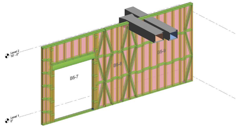
Pre-coordination between all trade contractors interacting with the CFS panels can be a critical contributor to the success of a prefabricated panel project. Early inclusion of the panel supplier into the project team allows for coordination with mechanical, electrical, plumbing, and fire protection trades regarding penetrations through walls, floors, and shear walls. Trade coordination is often performed through a shared building information model (BIM) administered by the general contractor or the project manager. BIM has proven to be a successful tool for handling such coordination. Figure 6 shows an example of a detected clash between a CFS wall panel and an MEP component that needs to be resolved.
Pre-coordination with other structural members is also critical. For example, if the design requires concrete shear walls or structural steel beams and columns outside the panels, the construction sequence and accommodations for tolerances need to be determined. At times, accommodating structural steel and concrete tolerances can be difficult, and a project team may decide that field-building those portions of framing is better. Otherwise, the general contractor must hold the steel and concrete trades to a tighter installation tolerance.
Another example of coordination with structural members is anchoring to a post-tensioned concrete deck, as the typical tendon layout will not allow anchors with an embed greater than 3⁄4 inch. Thus, either the tendons will need to be located after the pour with a method like ground penetrating radar or embed plates will be required along the length of the walls. Both options can be costly. An alternative is for the PT tendons to be designed with a thicker cover at the top of the slab, allowing standard post-installed anchors.
Fabrication, Lifting, and Trucking
In a panel, the various framing members (studs, tracks, headers, jambs, etc.) must all be positively connected to transfer the gravity and lateral forces. Two common connectors are screws and welds. They each have their advantages and disadvantages. Screw connections are easy to fabricate and don’t require a special certification. However, screwed panels are less rigid than welded panels. When welded connections are used, the panels are typically stiffer, which is beneficial in trucking and installation. However, welded connections make field adjustments difficult.
Many panelizers use jigs to build their panels. These can be a simple 90-degree frame to ensure the squareness of the panel and saw horses to raise the panel to a better working height. Or motorized framing tables can be used to help ensure the straightness of the panels and assist with seating the studs/joists in the tracks. The motorized framing tables can help build a higher-quality panel but can make installing connections on the backside of the panel challenging and limit the size of the panel being built.
Given the thin-wall nature of CFS framing, special care must be taken when lifting panels. Attention is usually given to lifting panels in the field, but the moving of panels in the fabrication facility can be just as tricky. For example, using a forklift to move wide panels around can lead to a bending failure of the top and bottom track if the members are not sized to support the cantilevered weight. When lifting a panel with chains/cables, it is critical to use proper connectors with appropriate safety factors in the field and the fabrication facility. It is also important to consider the various lifting conditions that the connectors will experience. For instance, if a panel is lifted from the horizontal position, the loading on the connector is very different than when the panel is in the vertical position. Finally, the increased load on the connectors due to the angle of the lifting cable is another essential element not to forget. Spreader bars can be used to enlarge the angle between the lifting cable and the top of the panel to minimize the increased load.
Trucking the panels from the fabrication facility to the job site is important to consider. Many states allow up to 14.5-foot-wide loads. However, these require special permitting, and some jurisdictions limit the times and days when these wide loads can travel. Panels under 8.5 feet wide usually do not require a special permit, but using this limited width increases the number of panels on a project which can increase the installation time.
Installation, Tolerances and Deviation from Location
Installation of the panels in the field is where all the hard work pays off. When properly coordinated and executed, CFS panels can be quickly installed in the field with a minimal crew. Often the panel installation can go fast enough that the panel fabricators need to have a large number of panels built before the start of installation.
While all projects allow for installation tolerances, it is essential to note that CFS framing usually supports drywall finishes that typically only allow a 1⁄8-inch-in-10-feet tolerance. This means it is critical that the CFS framing is accurately installed. This can be especially challenging when the tolerances for the concrete and structural steel elements are significantly less stringent.
When installing CFS panels, it is crucial to carefully install the lowest level of panels as they directly impact the panels above. Concrete podium slabs and slabs on grade can be quite wavy; thus, the lowest level of panels usually requires quite a bit of shimming and possible grinding down of the slab if there is an exceptionally high spot. Ensuring proper installation of the lowest level of panels can be quite tedious and time-consuming, but the rewards pay off during the installation of the upper panels.
Quality Control and Inspection
All fabrication facilities of CFS panels should have a fabrication procedure and quality control program. Section 1704.2.5 of the 2021 IBC allows the prefabrication of structural assemblies in the facility without special inspection if the facility is pre-approved by an approved agency or the building official. The pre-approval process is typically based on reviewing the fabricator’s written fabrication procedure, quality control manual, and periodic audits. An on-site inspection would still be required for any structural interconnection between prefabricated panels or connections with adjoining site-built structural components.
To develop off-site construction standards, a new standard from the International Code Council and Modular Building Institute, ICC/MBI 1200-2021, Standard for Off-site Construction: Planning, Design, Fabrication, and Assembly, has just been published. This standard provides a beginning step to defining the design, fabrication, transport, and on-site installation requirements of prefabricated components.
Concluding Remarks
This article presents the opportunity for off-site construction using prefabricated CFS load-bearing panels in mid-rise construction. This construction approach can help to optimize project construction schedules and address the shortage of on-site skilled workers and job site constraints. Pre-coordination and communication are keys to the success of this construction approach.■