
Welding is a fundamental part of steel construction, but correct performance at the steel fabricator’s shop and the project site requires effective communication of what’s expected. Following are some common mistaken assumptions on structural drawings regarding welding symbols. While most engineers are aware of the American Welding Society’s (AWS) D1.1, Structural Welding Code – Steel, many may not be aware that AWS produces a formal standard for welding symbols: A2.4 – Standard Symbols for Welding, Brazing, and Nondestructive Examination (Figure 1). When in doubt, this thoroughly illustrated reference is an excellent resource.
Assumption 1
I don’t need to show a fillet weld size.
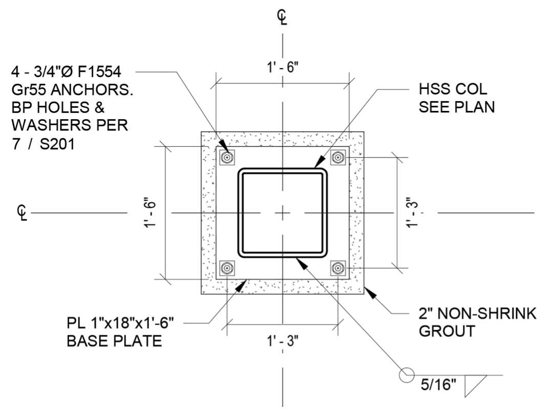
Structural drawings often include welding symbols with unspecified sizes. While a vee-groove weld without a specified throat or depth of preparation is assumed to be a Complete Joint Penetration (CJP) weld, fillet welds have no similar default. Lap joints for materials 1/4 inch or thicker have a maximum leg size of 1/16 inch less than the thickness of the overlapping part unless the weld is specified to be the full thickness of the part. This is not a default but simply a maximum. Specifying the full thickness is discouraged because of the tendency to melt the edge, blurring it and making an undersized weld appear full-thickness. Still, it is an option and a necessary one at times. Therefore, fillet weld sizes should always be specified clearly. Many fillet weld joints, such as the heel of an angle overlapping a gusset plate or a pipe column welded all around to a base plate, do not have any limiting dimension on the leg size other than a common sense guess that the Engineer of Record (EOR) did not need a 2-inch-thick fillet weld at the heel of an L2x2x1/4 kicker brace angle. The EOR is free to specify a typical size outside the welding symbol (such as in a note in the detail or on a general notes sheet), with the understanding that the further information is removed from the point of application, the easier it is to overlook discrepancies. The drawings should be carefully reviewed to verify that the typical size thus specified is adequate and actually achievable at the locations with blank welding symbols. See Figure 2 for a typical plan depiction of a fillet welding symbol.
Assumption 2
I don’t need to show a flare bevel groove weld size, or I can just say “full throat.”
Flare bevel and flare-vee groove welds are unique in that they are necessarily Partial Joint Penetration (PJP) groove welds, and therefore the effective throat must always be shown in parentheses. A groove weld size without parentheses denotes how deep the groove is and not the weld size and is simply the radius for flare bevel groove joints. For other groove welds, depth of preparation should not be specified unless the engineer knows the intended welding process (e.g., SMAW, FCAW, GMAW, SAW, etc.) and position (e.g., horizontal, overhead, etc.). Since the weld capacity is determined by the effective throat, and that depends on one factor known to the structural engineer (the radius of the member being welded) and on one factor known to the welding personnel (the welding process being used), the engineer must always specify the effective throat. Also, note that the AWS formulas for effective throat are based on the joint being filled flush; any depth of underfill must be subtracted from the theoretical throat. Generally, underfill is not a common design issue. However, questions of permissible underfill could arise due to potential repairs if an inspection revealed nonconforming welds or as a means of minimizing welding for large-radius members. See Figure 3 for a comparison of incorrect versus correct welding symbols. It is also worth noting that fillet welds in skewed T-joints have many of the same issues as the included angle increases above 100 degrees or decreases below 80 degrees. Therefore, that range of fillet welds also requires the engineer to specify the effective throat – not the leg size, as is typical for fillet welds. This is because there is a reduced throat dimension due to joint geometry for included angles above 100 degrees and a “Z-loss” dimension, which depends on the welding process used, for angles between 30 degrees and 60 degrees that must be accounted for. Fillet welds between 60 degrees and 80 degrees actually increase in effective throat relative to the leg size. Therefore, the engineer specifies the throat, and the shop/field welding personnel must determine the appropriate leg size based on the welding process employed.
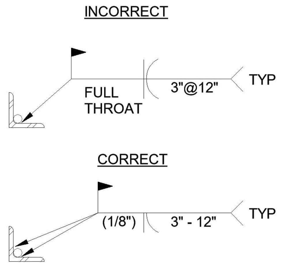
Figure 3. The top symbol shows a weld on the other side of the joint, which is behind the round bar and inaccessible. It also does not specify the effective throat correctly.
Assumption 3
The weld-all-around symbol is an acceptable shortcut at complex joints.
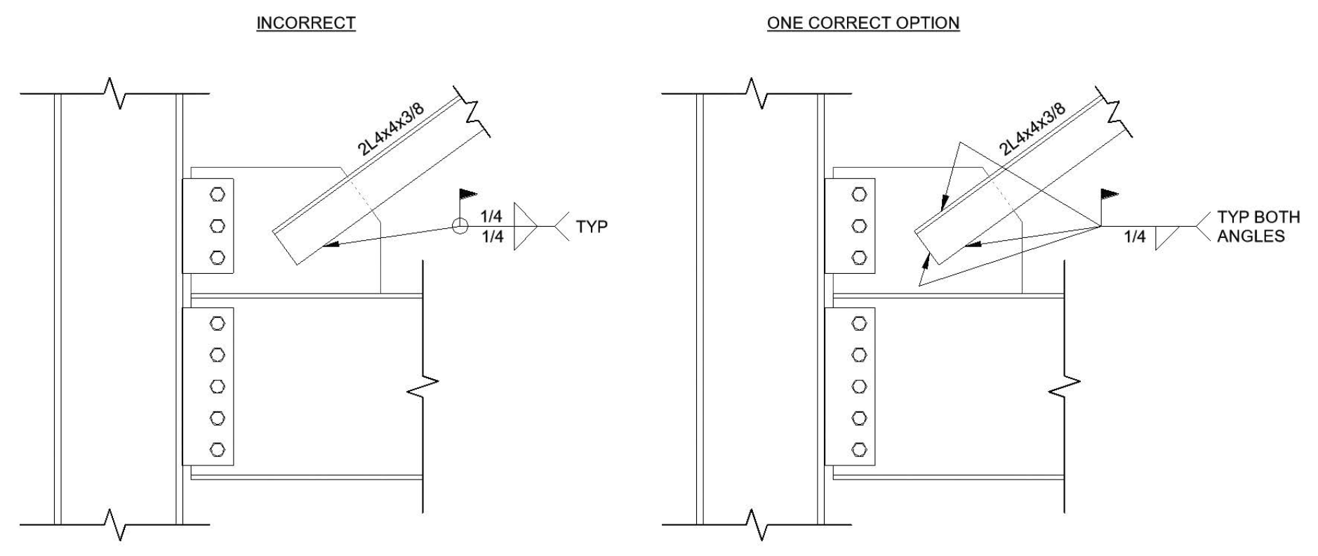
AWS actually restricts welding across the common plane (i.e., a “3-D” weld configuration) due to a) the likelihood of insufficient weld throat at the transition causing a potential weld failure under load and b) the masking of improper fitup. The need for actual continuous welds is recognized in D1.1 for conditions like airor liquid-tight sealing, hot-dip galvanizing, or sanitary washdown service conditions. However, in those cases, the burden is on the specifying engineer to note any required inspection (e.g., magnetic particle, liquid penetrant) at these joints due to the quality challenges mentioned. Yet this is precisely what engineers showing a weld-all-around symbol in some of their typical details are asking the welder to accomplish. See Figure 2 for an appropriate application of a weld-all-around symbol and Figure 4 for an inappropriate application. Other common misapplications of this symbol are when specifying the 3 fillet welds on a full-depth beam web stiffener or at square or rectangular HSS connections with flush members. In the latter case, the joint changes from fillet welds on two sides to flare bevel groove welds on the two flush sides.
Assumption 4
Arrow side/other side = near side/far side.
Another common assumption is that the arrow side (below the reference line) and other side (above the line) symbols are synonymous with near side and far side notation. However, while near side/far side is relative to the observer, the arrow side and other side are relative to the weld joint. For instance, if an angle is reinforced by welding a solid rod or pipe into the heel of the angle, the “other side” of the resulting flare bevel groove joint is actually the inaccessible one in the heel, not the separate joint at the other leg of the angle (Figure 3). Figure 4 also illustrates this distinction: the hidden angle on the far side of the gusset plate should be referenced in the tail rather than using a fillet weld symbol above the reference line.
Clear, correct welding symbols can take additional time to draw and additional space on already-crowded details. But engineers need to specify them accurately on their construction documents using the recognized standard on the topic to avoid ambiguity. Moreover, D1.1 requires welding symbols to conform to the A2.4 standard, making it legally binding in jurisdictions that adopt the International Building Code, incorporating D1.1 by reference. That can become especially important on projects with significant time and labor tied to welding if the design office and the shop or field interpret ambiguous welding instructions differently. ■