
The Midway Security Checkpoint Expansion Project
In 2016, the Chicago Department of Aviation (CDA) recognized that Midway International Airport (MDW) required expansion. Since September 11, 2001, the original narrow walkway connecting the landside and airside terminals over a major arterial street/ state highway was unable to meet enhanced security requirements, resulting in passenger backups into the adjacent parking garage.
The CDA awarded the Midway Airport Security Checkpoint Expansion project to Muller & Muller, Ltd. (M2) as a prime consultant in collaboration with Jacobs, serving as the bridge structure, civil/roadway, security, and wayfinding consultant. In this capacity, Jacobs designed the structure from the concrete deck level down to the foundation level, provided for utility relocation, designed the reconstructed roadway and sidewalks, coordinated with the Transportation Security Administration (TSA) for its needs for future security equipment, and worked with the client on ideal wayfinding throughout the new terminal. MDW’s location in a dense neighborhood required an innovative approach – expanding the airport’s footprint was cost prohibitive and would disrupt the surrounding community. Instead, using the existing walkway bridge, the Jacobs/M2 team created a new 80,000-square-foot structure that spans above and below active roadways (including during construction) to connect the MDW terminal’s two halves seamlessly.
Constructing Under the Upper-Level Roadway
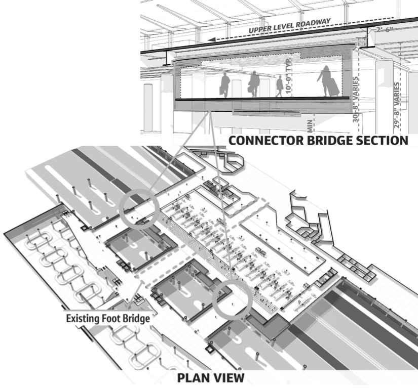
The initial CDA concept required construction under 400 linear feet of the upper-level departures roadway. However, the team suggested an approved alternative: two connector bridges – each approximately 50 feet wide (total of 100 feet linear construction under departures) connecting the new elevated security hall to the landside terminal (Figure 1).
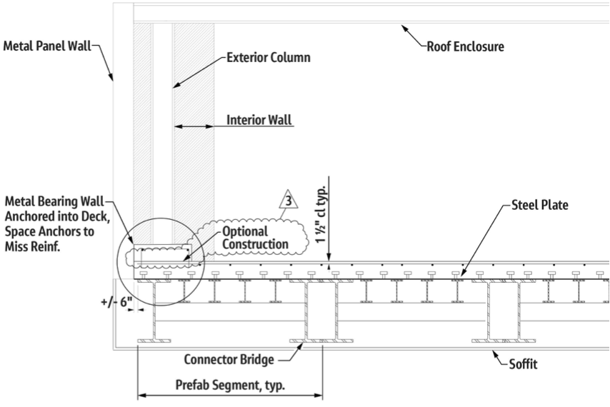
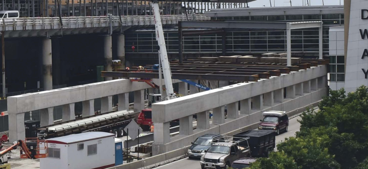
The vertical clearance from the bottom of the departures roadway to the top of the arrivals was too low for conventional cranes, so the team wrote a performance specification for prefabricated rolled beam bridges. The units were transported on a flatbed truck and installed side-by-side with a small crane under short interval closures of the arrivals lanes. The team used two 40-foot units to span the 80 feet between the landside terminal and the main bridge. Interior building columns are attached directly to the piers below. The team designed the exterior columns connection into a concrete curb on the beam bridges (Figure 2).
Distinctive Structural Engineering Obstacles
One unique project aspect was reviewing what design code to follow for building atop a bridge. The design team used the 2014 American Association of State Highway and Transportation Officials (AASHTO) load and resistance factor design (LRFD) Bridge Design Specifications, LRFD Guide
Specifications for the Design of Pedestrian Bridges, with adherence to the Chicago Building Code. The team quickly found that 100 pounds of force-per-square-foot (psf ) pedestrian loading (without live load reductions) and 125 psf in light mechanical areas controlled the design over the H10 maintenance vehicle from the Pedestrian Specification.
The team used complex construction staging to meet the CDA’s requirement for the checkpoint to be open continuously during construction, including utilizing Midas Civil to model the various construction stages for stresses in the deck and steel. While the original bridge supported pedestrians, Jacobs designed the north side steel using a splice point located east of Pier 2 (Figure 3); the erection of the remainder of the steel was followed by partial demolition of the airside terminal. Pedestrians utilized the north bridge after completion during the demolition of the original bridge portion up to a splice. The design called for existing and south bridge construction following partial demolition.
The team developed a framing plan to accommodate upper-level columns, roadway utilities, building column connections, and curtainwall with 34 uniquely sized and spaced beams. Jacobs modeled the deck using MIDAS Civil software to determine localized deck stresses from building columns and the long concrete piers (Figure 3) for thermal forces.
The TSA and curtainwall system mandated strict deflection limits of less than one inch total, requiring the team to design robust, shallow steel beams with camber. In addition, complying with the Americans with Disabilities Act (ADA) was a challenge, as the two building floors of the bridge were at different elevations. The team’s concept involved removing a portion of the original structure, splicing into the original steel, and then regrading with an ADA-compliant slope.
Incorporating Important Architectural Details
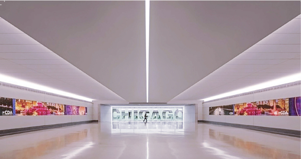
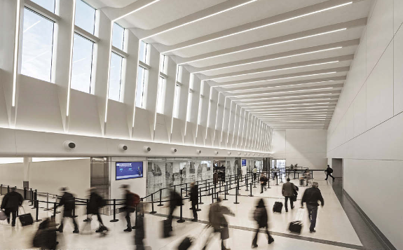
The new walkway offers an enhanced experience for passengers moving from the main ticketing hall to the queuing hall featuring integrated lighting in sculptural ceilings (Figure 4)
Bathed in natural light, passengers can look toward the soaring, cathedral-like ceiling heights and an extensive clerestory window wall that offers a view of the sky. Grace and beauty, combined with functionality and flexibility, create a positive welcome for travelers in Chicago.
Following an intensive 14-month design phase, the team overcame planning and technical challenges to create an iconic new gateway for the City of Chicago that opened in 2020 (Figure 5).
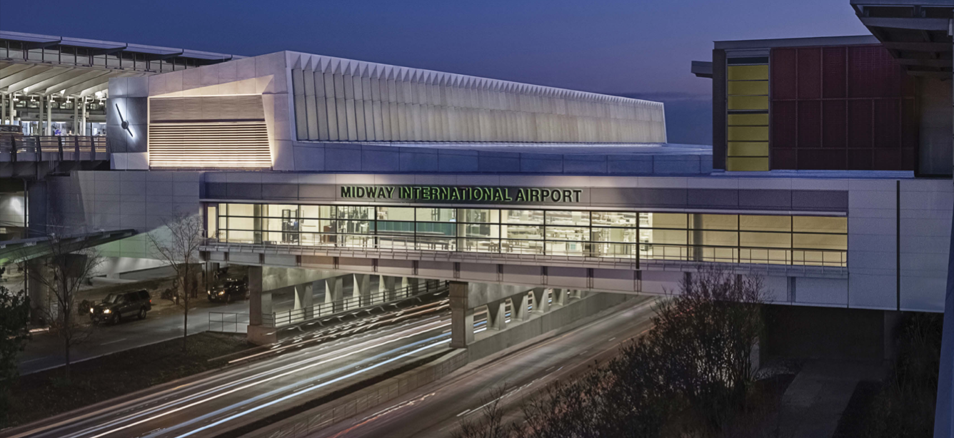
The resulting space addresses MDW’s capacity requirements and accommodates expanded future capacity. With reduced wait times, expanded retail and concessions, and an enhanced passenger experience, getting in and out of Chicago has never been easier!■
Project Team
Owner: Chicago Department of Aviation (CDA)
Architect of Record: Muller & Muller, Ltd. (M2)
Contractor: FH Paschen
Prime, Management, Architecture: Muller & Muller, Ltd. (WBE)
Civil, Bridge Structure, TSA Planning, Wayfinding: Jacobs
Building Structure: Matrix Engineering Corporation
Mechanical, Electrical, Plumbing: dbHMS (MBE)
Geotechnical: ECS Midwest, LLC
Surveying: Dynasty Group, Inc. (MBE)
SLighting Design: Schuler Shook
Cost Estimating: Faithful+Gould, Inc.
Building Envelope: Simpson Gumpertz & Heger
Acoustical: Shen Milsom & Wilke
Structural Software: – midas Civil, MDX