
This is a story about designing brick masonry curtainwalls. It is a story because the events did not all occur on the same project. They all happened, just on different projects.
For context and introduction, the author’s education is in solid mechanics followed by an early career in aerospace designing airplanes. Leaving the aerospace industry to design buildings wasn’t easy. Knowledge about the design of aluminum structures provided no respect from fellow building design engineers. When a small research project involving brick masonry came into the office, everyone else was suddenly too busy. The job turned out to be a blessing. It was easy to become an expert in masonry; there was no competition. There were also projects to design aluminum curtainwalls that no one wanted. Thus, by chance, the author evolved into a perceived expert in brick masonry curtainwalls.
Moving forward 10 years, an email arrived from one of our project managers. “Are you available for a meeting with the Contractor, Owner, and Design Team to talk about the brick exterior wall this afternoon?” “Sure, where?” The answer back is, “Don’t know yet – will let you know”. Two o’clock rolls around and we were off to the meeting.
The project is a large hospital, with over 500,000 square feet, in a seismically-active area that includes critical care, patient rooms, operating rooms and office space. The building is six stories with some five- and four-story sections and many corners. Our structural engineering firm had been working on the design with a noted architect for over six months. The gravity structural system is steel and the lateral system is concrete shear walls. The hospital is in a moderate-sized city that will service a large geographical area. The general contractor was on board, a large nationally known construction company, and the maximum project budget had been set. The architectural program was complete. A lot of effort had been expended on the design of the patient rooms. They were optimized for layout, including considerations of available cabinetry and other equipment, and were approved by the hospital management and staff. The dimensions were set and the owner had chosen a brick facade.
Twelve or more people were at the meeting, plus a video conferencing set-up to connect with the design architect in another city. A quick look at the drawings revealed the wall was a 4-inch brick veneer, with a 2½-inch insulated cavity, ½-inch exterior board and a 4-inch metal stud. Total thickness was 11 inches plus ½-inch interior wallboard for a total of 11½ inches. The brick dimension was 4-inch nominal, which meant the specified dimension is 4 inches minus the thickness of the mortar joint used to lay the brick, or 3-5/8 inches. The specified thickness of the wall was actually 11-3/8-inch. The floor-to-floor height varied between 13 feet 4-3/8 inches and 17 feet 4-3/8 inches, or 60 courses and 78 courses with an extra 3/8-inch for differential vertical movement between the floors. The architect obviously did this before [standard modular coursing, 3 courses per 8 inches].
A quick calculation using 20 psf [85+ miles per hour stagnation pressure] and 400S162-54 studs at 16 inches on center resulted in a deflection of 0.6 inches for the 13½ -foot story height and 1.7 inches for the 17½-foot story height. This is a deflection of approximately L/270 and L/120 respectively.
The contractor and architects seemed somewhat disconnected from the meeting. Only later did we learn the reason; this was the same wall system used on the previous job. One problem with being knowledgeable about masonry, you often are required to deliver bad news and often get shot as the messenger.
Everyone was looking at the expert when I declared: “The 4-inch stud thickness is not adequate to support the veneer. And, a brick veneer on steel studs cannot meet the seismic drift requirements at the corners for an essential building.”
The TV blinked and then went blank [it really did happen]. The lesson learned is to be less disruptive. It would have been much better to compliment the designers on their attention to modulation, ask what kind of brick [color] they intended to use and offer to look into the design. The bad news could then be delivered with a solution, and possible extra service fee at a later meeting.
Instead, the contractor took control with one of those harsh and elevated voices. “The dimensions of the wall will not change.” The meeting ended with our project manager promising to look into it.
There are standard criteria for the deflection of the veneer-backing wall. Unfortunately, the criterion don’t agree with one another. Numbers can vary between L/2000 to L/175. The International Building Code (IBC) does not provide a number. The L/2000 number will prevent any cracking of the brick veneer and the L/175 value is typical for the glass aluminum curtainwall industry. The Western States Clay Products Association recommends a value of L/360. The Brick Institute of America recommends a value of L/600.
Service wind loading was used for calculating the deflection limit. There is some room for interpretation of the service wind load definition. Most will use unfactored wind loading from ASCE 7 (Components and Cladding). But, the 85+ miles per hour wind has a return period of 50 years. Could a lower value be used?
Even at 50 miles per hour [stagnation pressure of 6.4 psf], the analysis predicts the brick veneer will crack [typically at the mortar joint]. But after cracking, the span is divided in half, which reduces the stress by a factor of 4. The consequence of a larger deflection is a larger crack opening [0.04-inch at L/360] and possibly more water infiltration as a result. The brick would remain attached to the backing studs because of the ties. But the wall will leak more.
With a high quality air and water barrier behind the brick veneer [the project was to have one], the criteria of L/270 and ASCE 7 unfactored loads worked for the 13½-foot story heights. This could be the solution.
The principal-in-charge jumped in. To stay within the standard of care usually exercised by structural engineers in the area at the time, the L/360 limit and ASCE 7 unfactored wind loading is common practice. Attorneys assessing the structural engineer’s performance relative to the standard of care often correlate more water to more deflection and if there is a water problem, then there is a structural problem and we would be sunk.
What were we going to do? The meeting was scheduled in two days and everyone was extremely unhappy with us for creating this problem. Not our fault, but perceptions are reality. Internal meetings considered many suggestions, including changing to another curtainwall material. But, the owner was set on brick. Could we use thin brick set in 7½-inch precast panels and forget about the cavity? This was rejected because of the weight impact on the seismic design and the appearance, which usually does not look natural, not to mention the loss of the 2 inches of insulation. We could also add a horizontal girt system below the floor at the ceiling level to reduce the span. This last option, while adding significant cost, was the selected solution and solves the deflection issue (Figure 1).
Figure 1. Girt system.
But what about the performance of the brick veneer at the building corners? For the walls that are linear, the horizontal joint between floors, filled with caulk, could accommodate the seismic movement. But the joint doesn’t work at a corner and there were a lot of corners. The IBC “accommodation” of the seismic displacement Dp of 1.5 inches. What does accommodation mean for a brick veneer? Other sections of the IBC imply that the performance for a glass curtainwall is that the glass does not fall out of the frame. Could we imply from this that the criterion for a brick veneer is that no brick falls out of the wall and cracking will be OK? All agreed that this criterion would be acceptable, including the principal-in-charge who then left the room.
How to meet the criteria was the hard question!
With the 1.5-inch displacement and ties close to the corner, all agreed that the ties would pull out of the masonry or disengage from the stud by stripping the screw or by a tension failure. Sections of the wall would likely disengage from the backing.
Was the requirement for #9 wire joint reinforcement to engage the veneer tie a solution? No! Recent research demonstrated that adding the #9 wire joint reinforcement in the veneer to engage the tie did not help, and may reduce the capacity of the tie. (The requirement is no longer in the 2013 edition of the IBC.) It was clear that the conventional detailing of brick veneer at the corner does not satisfy the criteria.
A suggestion was made to provide a control joint at the corner. This is a common solution. Architects hate the wide joints required, but sometimes accept them. The width of the joint would need to be 1½ inches or wider to allow for construction tolerances. Additionally, the joint would need to be close to the corner to minimize the stiffness of the return brick. The “eliminate the corner” option worked and sketches were prepared (Figure 2).
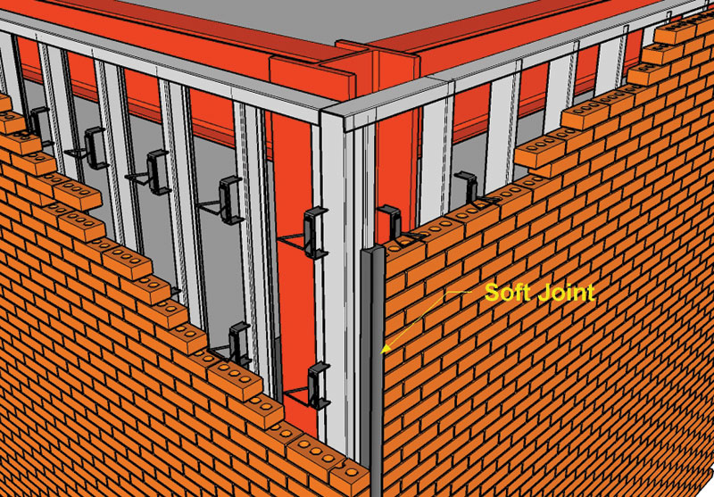
Figure 2. Soft joint corner.
Another engineer suggested isolating the backup stud wall system. This would require a detailed design of the stud wall. Bracing would be required and the stud-head-track would be designed not to attach to the floor above at the corner. This would also reduce damages to the interior finishes and the brick could be detailed as the conventional veneer (Figure 3).
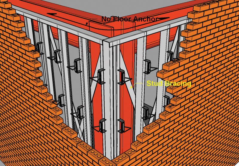
Figure 3. Isolated veneer backing.
The project manager piped in: “There is no fee for this in our scope of work.” A fee proposal would be required with this option, or it could be a bidder-designed item and we could let the architect put it into the specifications.
Oops, the principal-in-charge returned. “The bidder-designed option is not an option. I have been there before. The metal stud low bid sub-contractor will miss the requirement and have no money to do it right. This is the stuff claims are made of.”
The author suggested reinforcing the veneer as a possible solution. This concept would replace the ties with floor and girt connectors. The reinforced structural masonry would span to the connectors. Connectors could be placed a distance from the corners, allowing the deflection to occur by warping of the wall [like a curtainwall]. The savings from the elimination of the ties [stainless steel was contemplated] equaled or exceeded the added cost of grout and reinforcement. But, past experience with owners, contractors and architects was mixed. The concept of warping brick corners was difficult to explain. Moreover, some of our own SE’s doubted it would work. Brick is a brittle material.
“Is reinforced concrete a brittle material? Reinforced brick appears to demonstrate more flexibility in the curtainwall test conducted under AAMA 501.4 than reinforced concrete.”
Who would do the design? It was not in our scope.
Despite the doubt, a reinforced veneer is added as a solution along with a fee proposal (Figure 4).
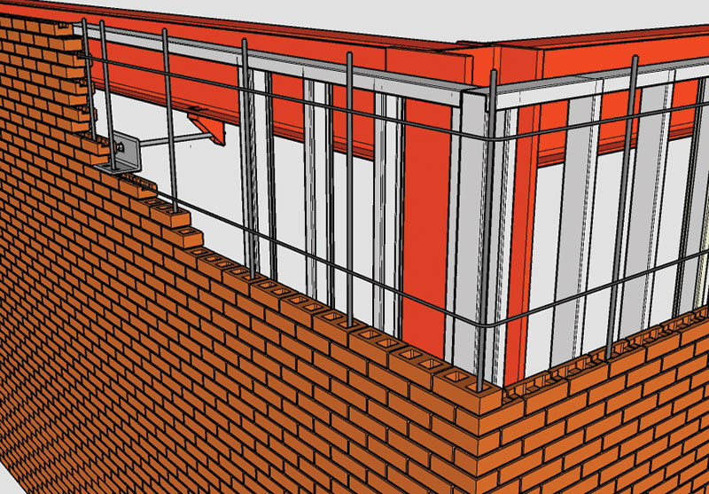
Figure 4. Reinforced veneer.
Sketches and presentation materials were prepared in a flat-out effort. With three proposals in hand, “elimination of the corner”, “isolated stud wall corner”, and “reinforced veneer”, we headed for the meeting, now at the owner’s headquarters.
The air was thick. The perception was that this entire mess belonged to us. The General Contractor invited the CEO for the owner, and the design architect flew in from the far-away city. A mason contractor was invited to participate. The meeting began …….
The story doesn’t end here, just this article.
Structural engineering is a great profession. Each situation is different and we get to solve many problems, most of them created by our clients. But, each day is different and in the end we get to participate in the creation of great projects.▪
Post Script: Don’t put a deflection limit in the IBC. One criterion does not work for all projects and clients. Moreover, adding a prescription to the code eliminates the opportunity to be creative. I prefer to be a consultant that uses judgment and experience to customize designs and recommendations for my clients. And, it offers the opportunity for a design fee that adds value to the project.
For more information on Reinforced Brick Veneer, see the Design Guide for Structural Brick Veneer from Western States Clay products Association.