
Erratum
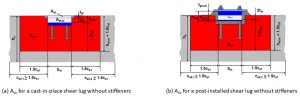
Figure 2(b) and Figure 3(b) in the article incorrectly show the bearing area (Aef,sl) as a T-shaped configuration. This configuration is only relevant when stiffeners are used.
Since the shear lug in these illustrations does not include stiffeners, the bearing area (Aef,sl) should be shown as a rectangular configuration. If stiffeners are installed, the leading edge of the stiffener and the area of the shear lug extending 2tsl on either side of the stiffener would be included in Aef,sl. The author apologizes for any confusion this may have caused. (This Erratum has been added to the online version of the article, www.STRUCTUREmag.org.)
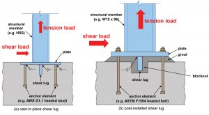
A shear lug is a steel embedment used as part of an anchorage to transfer shear loads into a concrete foundation. In the context of this article, an anchorage is comprised of 1) a structural member subjected to tension and shear loading, 2) the base plate to which the member is attached, 3) one or more shear lugs welded to the base plate, and 4) cast-in or post-installed anchors. Depending on how the connection is detailed, anchors may share in resisting applied shear loads, or they may be designed only for tension load on the connection such that the entire shear demand is assigned to the shear lug.
Shear lug provisions have been introduced into the American Concrete Institute (ACI) publication Building Code Requirements for Structural Concrete (ACI 318-19). This article discusses these provisions and how they can be integrated into anchorage design.
Shear Lug Provisions
ACI 318-19, Chapter 17, addresses anchoring-to-concrete. Section 17.11 – Attachments with shear lugs has been added in this code version. It references two types of shear lugs welded to a base plate: cast-in-place shear lugs and post-installed shear lugs. Cast-in-place shear lugs are cast into the concrete, as shown in Figure 1a. Post-installed shear lugs are grouted into a keyway or “blockout” in the concrete, as shown in Figure 1b. Shear lugs are oriented perpendicular to the direction of the shear load. If shear load acts in more than one direction, shear lugs having a cruciform (i.e., a cross shape) or a square shape can be used to resist the shear load component in each direction.
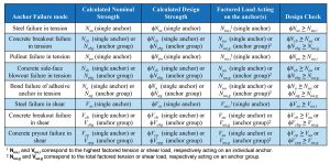
ACI 318-19 Chapter 17 design provisions for cast-in-place and post-installed anchors consider possible tension and shear failure modes, for which an anchor design strength is calculated. The design strength is checked against a factored load. The Table summarizes these anchor design provisions.
ACI 318-19 Section 17.11.1 includes general provisions for designing shear lugs. Section 17.11.1.1.2 requires a minimum of four anchors to be provided in the anchorage. This section also states that anchor failure modes associated with shear loading do not need to be checked; therefore, the shear lug is assigned the entire shear demand. However, for base plates with rigidly attached anchor elements, Section 17.11.1.1.3 and the commentary R17.11.1.1.3 note that displacement of the plate in response to shear loading induces anchor deformations that must be accounted for. Anchors subjected to tension loads must still be designed for the relevant tension failure modes noted in the Table.
Section 17.11 shear lug provisions include two design checks: one for bearing failure and one for concrete breakout failure. Bearing failure provisions are given in Section 17.11.2, and concrete breakout failure provisions are given in Section 17.11.3. Per Sections 17.11.1.1.4 and 17.11.1.1.5, a nominal strength for bearing failure (Vbrg,sl) is calculated and multiplied by a strength reduction factor (φ-factor) of 0.65 to obtain a design strength (φVbrg,sl). Per Sections 17.11.1.1.6 and 17.11.1.1.7, a nominal strength for concrete breakout failure (Vcb,sl) is calculated and multiplied by a strength reduction factor (φ-factor) of 0.65 to obtain a design strength (φVcb,sl). Each design strength is checked against the factored shear load (Vu) acting on the anchorage. If φVbrg,sl ≥ Vu and φVcb,sl ≥ Vu, the provisions are satisfied. Section 17.11 provisions only consider concrete failure modes for shear lugs; reference the American Institute of Steel Construction (AISC) publication Steel Design Guide 1: Base Plate and Anchor Rod Design, Second Edition, for information on sizing the shear lug and designing the welded connection between the shear lug and plate.
Bearing Strength in Shear of Attachments
Bearing failure for a shear lug occurs at the shear lug/concrete interface such that a fracture surface develops in the concrete in front of the shear lug. Section 17.11.1.1.2 notes that shear failure modes for anchors are not considered; however, the commentary R17.11.1.1.3 notes that anchors welded to a plate are placed in bearing as the fracture surface develops because the anchors displace with the plate. Therefore, if tension and shear (bearing) loads act on an anchorage consisting of anchors welded to a plate/shear lug assembly, Section 17.11.1.1.3 requires a combined load interaction check on the anchors. This check is only noted for anchors that are welded to a plate/shear lug assembly.
Equation (17.11.2.1) defines the nominal bearing strength of a shear lug (Vbrg,sl) as:
Vbrg,sl = 1.7 f´cAef,sl Ψbrg,sl Equation (17.11.2.1)
where:
f´c = specified concrete compressive strength
Aef,sl = effective bearing area of the shear lug
Ψbrg,sl = modification factor for axial load acting on the anchorage
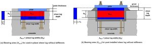
(Figure updated to reflect erratum.)
The parameter (Aef,sl) is defined by the width of the shear lug perpendicular to the direction of the applied shear load and a projected distance based on twice the shear lug thickness (tsl). Aef,sl for a typical cast-in-place shear lug (red shaded area Figure 2a) does not include the embedded plate. Aef,sl for a typical post-installed shear lug (red shaded area Figure 2b) does not include the portion of the shear lug above the surface of the concrete or the plate. If stiffeners are installed perpendicular to the face of the shear lug, the leading edge (i.e., thickness) of the stiffener would be included in the Aef,sl calculation.
The modification factor (Ψbrg,sl) considers the influence on shear lug bearing strength from confinement effects. Part D.11.1 in the ACI publication Code Requirements for Nuclear Safety-Related Concrete Structures (ACI 349-13) defines confinement effects as “the confinement afforded by the tension anchors in combination with external loads acting across potential shear planes.” ACI 318-19 calculations for Ψbrg,sl only consider external axial load (Pu) acting on the anchorage. An external moment that creates tension in some anchors and compression in front of the shear lug across the potential fracture surface is not considered in the calculation of Ψbrg,sl.
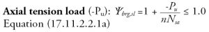
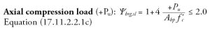
Equation 17.11.2.2.1a is used to calculate Ψbrg,sl when axial tension acts on the anchorage. Pu is negative in this equation, and the calculated value for Ψbrg,sl is less than or equal to 1.0. Equation 17.11.2.2.1c is used to calculate Ψbrg,sl when axial compression acts on the anchorage. Pu is positive in this equation, and the calculated value for Ψbrg,sl is greater than 1.0. If no axial load acts on the anchorage, Ψbrg,sl equals 1.0 per Equation 17.11.2.2.1b.
where:
Nsa = anchor nominal steel strength in tension
n = number of anchors in tension
No axial load: Ψbrg,sl = 1 Equation (17.11.2.2.1b)
where:
Abp = area of base plate
Per Section 17.11.2.4, if multiple shear lugs oriented perpendicular to the direction of the applied shear load are used, Vbrg,sl for each shear lug may be summed to give a total bearing strength, provided the stress on a shear plane in the concrete at the bottom of the shear lugs, and extending between them, does not exceed 0.2f ´c.
Concrete Breakout Strength
Concrete breakout failure for a shear lug occurs at a concrete edge when the shear load acts towards the edge. ACI 318-19 Section 17.7.2 is titled Concrete breakout strength of anchors in shear. Equation (17.7.2.1a), used to calculate nominal concrete breakout strength in shear of a single anchor (Vcb), is given as:
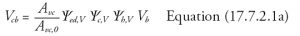
Per Section 17.11.3.1, this equation’s parameters are modified with shear lug parameters to calculate the nominal concrete breakout strength for a shear lug (Vcb,sl).
The parameter AVc in Equation (17.7.2.1a) corresponds to the projected failure area on a fixed concrete edge in the direction of the applied shear load. AVc for a shear lug is defined by projected distances of 1.5ca1 on each side of the shear lug and 1.5ca1 beneath the effective embedment depth of the shear lug (hef,sl). The distance in the direction of the applied shear load from the bearing surface of the shear lug to the fixed edge is represented by ca1. The parameter AVc0 in Equation (17.7.2.1a) is given in Equation (17.7.2.1.3) as:
AVc0 = 4.5 (ca1)2 Equation (17.7.2.1.3)
where ca1 for a shear lug design is defined above.
(Figure updated to reflect erratum.)
The red shaded areas in Figure 3 illustrate how the geometry to define AVc for a shear lug is determined. The effective bearing area (Aef,sl) for each type of shear lug shown is shaded in white to emphasize that it is not included in the calculation of AVc. The embedded portion of the plate above the shear lug (white shaded area Apl in Figure 3a), is likewise not included in the calculation of AVc.
Concrete thickness (ha) must be considered when calculating AVc. If ha is less than (hef,sl + 1.5ca1), the calculated value for AVc will be limited by ha.
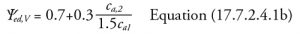
Ψed,V is a modification factor for a fixed edge distance perpendicular to the direction of the applied shear load (ca2) that is less than 1.5ca1. If ca2, as shown in Figure 3, is less than 1.5ca1, Ψed,V is calculated per ACI 318-19 Equation (17.7.2.4.1b):
If there are multiple fixed edge distances perpendicular to the direction of the applied shear load that are less than 1.5ca1, the smallest value is used to calculate Ψed,V.
Ψc,V is a modification factor for cracked or uncracked concrete conditions. Reinforced concrete is assumed to crack under service loads. Uncracked concrete can be assumed where analysis indicates no cracking under service loads. The default Ψc,V value equals 1.0 for cracked concrete conditions. Ψc,V can be increased to 1.4 if uncracked concrete conditions are assumed.
Ψh,V is a modification factor for a thin concrete member, such as a slab (Figure 3). If ha is less than (hef,sl + 1.5ca1), Ψh,V is calculated per a modified ACI 318-19 Equation (17.7.2.6.1) that includes the parameter hef,sl.
When calculating nominal concrete breakout strength for a shear lug (Vcb,sl), the parameter Vb (basic concrete breakout strength) is calculated using Equation (17.7.2.2.1b). This equation is an anchor equation, but, for shear lug design, the parameter ca1 corresponds to the distance in the direction of the applied shear load from the bearing surface of the shear lug to a fixed edge. λa is a modification factor for lightweight concrete.

Special cases for concrete breakout occurring at a fixed edge parallel to the direction of the applied shear load (Figure 4a), shear lug located in a corner (Figure 4b), and multiple shear lugs (Figure 4c)
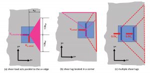
are covered in ACI 318-19 Sections 17.11.3.2, 17.11.3.3, and 17.11.3.4, respectively. Note that the actual direction of Vu in Figure 4a is in the y+ direction, but Vcb,sl is calculated as if Vu acts towards the x+ edge and ca1 is taken from the center of the shear lug. Vcb,sl for shear load acting towards the x+ edge and parallel to the y+ edge would have to be considered for the case shown in Figure 4b. Vcb,sl towards the x+ edge is calculated for each shear lug in Figure 4c, and the smaller value is used for design.
When to Use Shear Lugs?
Shear lugs can be used in an anchorage 1) when a calculated shear design strength for the anchors is less than the factored shear load assumed to be acting on them, 2) when the number of anchors needed for shear transfer is impractical, or 3) when alternative means for shear transfer into the concrete is desired.
Per the Table, concrete breakout is a failure mode considered in ACI 318 anchoring-to-concrete provisions. When concrete breakout in shear occurs, a failure surface in the concrete develops from anchors resisting shear load to a free edge in the concrete. Anchorages to pedestal foundations often involve small anchor edge distances, such that anchor resistance for shear loads is severely limited by the possibility of concrete breakout occurring at an edge. If the calculated design strength for concrete breakout in shear (φVcbg) is less than the factored shear load assumed to act on the anchors (Vua), ACI 318-19 anchoring-to-concrete provisions for concrete breakout in shear are not satisfied. The use of a shear lug in the center of the pedestal, with the anchors devoted solely to resisting uplift tension, offers a design solution for the shear demand.
Figure 1b illustrates anchors installed with standoff. When anchors are installed with standoff and subjected to shear load, bending stresses develop in the anchors. Anchor resistance to bending depends on the material properties of the anchor element, its geometry, the amount of standoff, and the amount of rotational restraint acting on the anchor. An anchor bending resistance can be calculated as a steel design strength in shear using these parameters and checked against a factored shear load.
ACI 318-19 Section 17.10, Earthquake-resistant anchor design requirements, includes provisions for designing anchors to undergo tension yielding in response to earthquake loading. Designing anchors with a stretch length permits energy dissipation via the anchors. Stretch length can be obtained by designing an anchor chair in conjunction with a grouted standoff. Shear load acting on the anchorage would subject the anchors to bending stresses. If the calculated anchor bending resistance is less than the factored shear load assumed to act on the anchorage, a post-installed shear lug offers a design solution for the shear demand.
Putting it Into Practice
Anchoring-to-concrete calculations can be quite involved. Consideration must be given for a multitude of anchor failure modes and design parameters. Many engineers use anchor design software to perform these calculations. Shear lug design requires sizing the shear lug, designing welded connections, and calculating design strengths for bearing and concrete breakout failure. Software capable of performing anchoring-to-concrete and shear lug calculations can reduce the time and effort spent designing an anchorage.
Summary
ACI 318-19 has included a new section (Section 17.11) titled Attachments with shear lugs that contains design provisions for shear lug concrete failure modes. This article provided an overview of the provisions given in Section 17.11 and discussed how a shear lug could be integrated into an anchorage design when the shear demand on the anchors is exceeded.■