
One could argue that drift loads are the most important snow load since they account for roughly 75% of all snow-related structural problems. The various types of roof snowdrifts are reasonably well understood. However, a new snowdrift was recently observed downwind of a run of roof-top refrigeration piping, which did not seem consistent with our current understanding of snowdrift formation. In this article, the drift formation processes for four common snowdrifts – leeward roof step drifts, gable roof drifts, windward roof step drift, and parapet wall/roof projection drifts – are reviewed as well as the apparent formation process for the new roof-top piping-run drift. Finally, an explanation for the apparent inconsistency between the new piping-run drift and common drifts is provided.
Leeward Roof Step Drifts
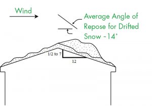
Leeward roof step drifts are comparatively straightforward. The trapping efficiency (percent of windblown snow arriving at the geometric irregularity which remains at the geometric irregularity) is taken to be about 50%, based on water flume studies. The fetch is the horizontal extent of the roof upwind of the step. These drifts have a nominal right triangular shape throughout the drift formation process, with the peak drift depth located adjacent to the step, as shown in Figure 1.

The drift slope is initially about 1 on 4 (14º), which is thought to be the average or typical angle of repose for drifted snow. This slope is maintained while the drift height is less than the step size. When the drift reaches the top of the step, the slope begins to flatten as the drift continues to grow downwind. When the slope reaches about 1 on 8 (7º), the drift shape becomes streamlined, and drift growth nominally terminates as the geometric irregularity has been eliminated. That is, absent the snowdrift, mean wind streamlines attach to the lower level roof at roughly 8 roof steps downwind.
Gable Roof Drifts
Although often referred to as unbalanced loads, gable roof drifts are actually across-the-ridge leeward drifts. Water flume studies suggest that the trapping efficiency of gable roof drifts is nominally the same as that for leeward roof step drifts. In the American Society of Civil Engineers’ ASCE 7, Minimum Design Loads and Associated Criteria for Buildings and Other Structures, the cross-sectional area of a gable roof drift is close to and based upon that for a leeward roof step drift with the upwind fetch being the eave to ridge distance for the gable.
Gable roof drifts have a non-right triangular shape, as shown in Figure 2. The top surface is more or less flat, with the bottom surface matching the roof slope and the downwind surface having a slope approximating the angle of repose of drifted snow. Although observed gable roof drifts have a non-right triangular shape described above, they are currently approximated in ASCE 7 by a rectangular surcharge, with an aspect ratio being a function of the roof slope – longer horizontal extent and shallower depth for lower roof slopes.
Gable roof drifts typically do not form if the roof slope is too shallow (less than ½ on 12) or too steep (greater than 7 on 12). At the lower limit, the roof is so flat that there is no flow separation at the ridgeline, and the attached flow eliminates the aerodynamic shadow where the drift would form. This is generally consistent with the maximum angle of about 4° for the expanding portion of a venturi tube or diffuser to avoid flow separation. Note that the total change in roof pitch at the ridge (upslope at ½ on 12 to downslope at ½ on 12) is about 5°. At the upper limit (greater than 7 on 12), the roof is steeper than the maximum (unlikely to be exceeded) angle of repose for drifted snow (taken to be about 30°). In this case, there would be flow separation at the ridge, and an area of aerodynamic shadow would form downwind of the ridge, but the wind transported snow particle will either roll off or not “stick” to the steep roof.
Windward Roof Step Drifts
The formation process for windward roof step drifts is more complex than that for leeward drifts because of the presence of a separated flow region and an eddy or trapped vortex upwind of the step that initially drives snow out of that region. The initial drift shape is non-right triangular, as shown in Figure 3. For 3-D obstructions such as poles or posts, the eddy is termed a horseshoe vortex because of its plan shape. The trapped vortex initially prevents snow accumulation in this region and leads to the peak drift initially being about one step height upwind of the step.
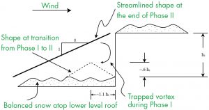
During this initial phase of windward drift formation (Phase I), the wind-transported snow layer, e.g., the saltating snow particles, are within the wind streamlines that notionally enter the upwind separated region. As such, nearly all of the snow particles stay upwind of the wall, and hence, the trapping efficiency becomes nominally 100%.
If strong winds persist (wind speeds greater than about 10 mph), the windward drift upwind of the step continues to grow, forming a snow ramp that effectively “fills in” the upwind separation region. This process weakens the trapped vortex and eventually eliminates it. Then the saltating snow particles join the wind streamlines flowing over the step. At this point, the 100% trapping efficiency phase (Phase I) ends, the trapped vortex at the step begins to fill with snow, and the trapping efficiency drops to approximately 20% (80% of the saltating snow particles flow over the step). During this next phase, the windward drift’s shape morphs from its initial non-right triangular shape (Phase I) to a right triangular shape (Phase II), with the peak drift depth being at the step.
If strong winds continue and the snow source remains un-depleted, the Phase II windward drift becomes aerodynamically streamlined when the drift reaches the top of the wall and the slope is about 1 on 8. At this point, the geometric irregularity has been removed and additional drift formation ceases.
Parapet Wall and Roof Projection Drifts
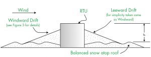
By their nature, the snowdrifts at parapet walls and upwind of roof-top units (RTUs) are windward drifts. For RTUs, drifts also form simultaneously at the downwind side, as shown in Figure 4. However, for simplicity, ASCE 7 specifies the upwind side windward drift for that location as well. Recently, ASCE 7 has addressed the issue of mitigation of snow drifting at RTUs. In particular, if the RTU is raised 2 feet above the balanced snow, this vertical gap is assumed to prevent drift formation at the RTU. This provision is advantageous if a smaller RTU on an existing roof is replaced by a new, larger, and heavier RTU.
Unexpected Drift
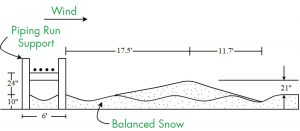
The authors became aware of an unusual roof-top snowdrift during a recent forensic investigation in the Midwest. As shown in Figure 5, the snowdrift formed downwind of a run of roof-top cooling pipes. Somewhat surprisingly, the total load, in pounds per foot (lbs./ft.), for the piping-run drift was comparable to that for a leeward roof step drift with the same upwind fetch and design ground snow load. There were several reasons why the drift was both unusual and unexpected. First of all, the drift was centered about 17 feet downwind of the downwind edge of the piping-run. Hence, unlike the well-known leeward roof step and gable roof drifts described above, the downwind piping-run drift was well removed from the geometric irregularity (i.e., the piping run itself). This contrasts with the common leeward drifts described above, which form adjacent to the geometric irregularity. Furthermore, the vertical gap between the bottom of the pipes (pipe diameter nominally 6 to 12 inches) and the top of the balanced snow surface was about 2 feet. This seems to contradict the recent ASCE 7 provisions for elevating RTUs to avoid windward and leeward drift formation.
It should be mentioned that, as part of the forensic investigation, it seems that one structural engineer involved with refrigerated storage facilities design had observed similar roof-top piping drifts in the past. A 2003 report by Ronald Tabler, Controlling Blowing and Drifting Snow, prepared for the National Cooperative Highway Research Program for the Transportation Research Board of the National Academies, presents photographs of drifts downwind of box beam and W beam roadside guard rails. Hence, the snowdrift shown in Figure 5 is not an aberration.
At first, the authors thought the piping-run drift to be an anomaly. However, over time, a plausible explanation for the drift’s “unusual” aspects developed.
One would initially anticipate that snow drifting around roof-top piping would behave similarly to drifting around RTUs. Both provide an obstruction to roof-top wind flow. However, since the piping’s crosswind extent is much larger than an RTU, the piping is nominally a 2-D obstruction rather than a typical RTU, which would be considered a 3-D obstruction. Wind flow over the top and around the sides of a typical RTU results in two aerodynamic shadow regions – one immediately upwind and the other immediately downwind where drift formation occurs. A downwind region of reduced wind speed – a wake region – exists at an RTU, but the downwind extent of the wake region behind the piping-run extends further downwind than that of the RTU. As opposed to forming an adjacent aerodynamic shadow, piping-run drifts form well downstream of the obstruction due to the reduced speed and increased turbulence in the wake.
In relation to the drift mitigation gap for a raised RTU, the wind flows beneath the unit as well as over the top and around the sides. The gap and resulting flow below an elevated RTU eliminates the aerodynamic shadow regions and hence eliminates drift formation on both the upwind and downwind sides of the RTU. Artic buildings are often placed on stilts for this very purpose. This is consistent with the observed behavior of the elevated piping run; specifically, there was no upwind or downwind drift accumulation immediately adjacent to the obstruction.
As mentioned above, in relation to Figure 5, the gap between the piping run and the snow surface is about 2 feet. Hence, the wake region behind the pipes was reasonably close to the saltating snow particle layer adjacent to the snow surface. If the gap between the piping run and the snow surface were much larger (say 10 feet or more), the wake region would be well above the saltating snow layer. For such a case, this type of snowdrift would be much smaller or non-existent.
Summary
This article describes a newly observed roof-top piping-run drift and compares it to common windward and leeward drifts in ASCE 7. Since there is currently only a single reasonably well-documented case history, the specific influence of certain key parameters is not well understood. If and when additional case histories become available, future versions of ASCE 7 may well address this new and interesting snowdrift.■