
A Brief Summary
Bored piles, also referred to as auger-cast piles, are large-diameter cast-in-place concrete piles used commonly to support buildings when column loads are high. The design of bored piles requires the designer or the project’s geotechnical engineer to estimate the load-carrying capacity of the pile based on the ground conditions at the project site. One way to predict the pile capacity is by carrying out calculations using soil parameters obtained from site investigation data. While many pile design methods are highly empirical, pile capacity can also be affected by other factors such as the method of installation, quality of workmanship, and construction materials used. Therefore, pile load testing is an essential aspect of pile design that should not be overlooked.
This article summarizes pile load testing (static type using a kentledge) for bored piles in soil and highlights some key aspects designers should look for when reviewing and interpreting pile load test results. For more information on pile design, the reader is directed to Pile Structural Capacity – A Comparison of Three Design Codes published in the March 2020 issue of STRUCTURE.
Types of Load Tests
There are essentially two main types of pile load tests: the preliminary pile test and the working pile test. A preliminary pile test is typically carried out before the piling works commence while the working pile test is carried out during piling or when substantial piling works are completed. When using limit state design (e.g., Eurocode 7-EC7), the preliminary pile test and working pile test allow designers to adopt less conservative partial factors when reducing unfactored shaft friction and end-bearing, resulting in a more economical design. Similarly, when using LRFD design or ASSHTO specifications, more load testing may allow a higher resistance factor (φ) to be used due to the increased reliability.
The preliminary pile test verifies the design parameters prior to the start of piling work. Therefore, the test pile is instrumented so that assumed values of shaft friction and end-bearing could be verified. A borehole close to the pile location is necessary to ascertain the type and layering of the soil for verification. Strain gauges are installed at intervals throughout the length of the pile so that the force for each segment can be calculated and the pile’s load transfer can be obtained. The same pile installation method should be used to install the working piles for the project. To adequately verify the shaft friction and end-bearing capacity, preliminary piles are typically loaded to 3 times the working load.
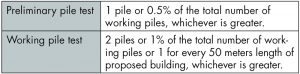
Working pile tests are conducted during piling work to verify the quality and workmanship of the installed piles. These tests verify that installed piles perform as-designed to meet strength (ability to carry load) and serviceability criteria (with acceptable settlement). Working piles are loaded progressively, with the load and pile head settlement monitored and recorded. The acceptance criteria for working piles are settlement limits at certain loads. For example, in CP4 (SS CP4 Code of practice for foundations, Singapore Standard), the settlement cannot exceed 0.59 inches (15mm) at 1.5 times the working load or 0.98 inches (25mm) at 2 times the working load. The higher allowable value of settlement at 2 times of working load is to recognize that, at higher loads, the rate of increase in settlement is likely to be greater. Recommendations for the number of tests are shown in Table 1.
Load-Settlement Curve
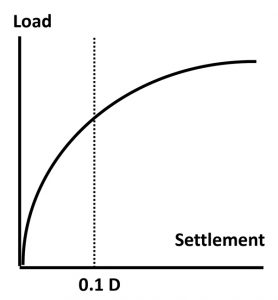
A simplified load-settlement curve is shown in Figure 1. Generally, the curve is non-linear, and the stiffness of the response tends to degrade or soften as the load gets higher. This is expected because, as the load increases, the pile approaches “failure” in geotechnical terms. Some codes define the “failure” of a pile as reaching a settlement of 10% of pile diameter. For large diameter piles, this criterion becomes somewhat lenient if the serviceability limit state is considered. For example, a 39.37-inch-diameter (1000mm) bored pile has an allowable settlement of 3.94 inches (100mm). The settlement acceptance criterion has to be stringent because pile settlement can result in a differential settlement between supports, which is a grave concern due to the amplification of tilt for a tall superstructure. In addition, building settlements may disrupt utilities and services (e.g., pipes and cables). Therefore, a much smaller value of the allowable settlement is usually required.
Piles rarely “fail” with regard to vertical structural capacity. In a case study presented later, a quick calculation shows that the axial stress in the pile at its rated working load is on the order of about 8 to 10 MPa (or 1.2 to 1.5 ksi).
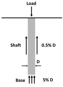
A critical aspect of pile design is shown in Figure 2, where the load on a pile installed in soil is resisted by a combination of shaft friction and end-bearing. As the pile is loaded, shaft friction increases gradually and can become fully developed by a small movement of approximately 0.5% of pile diameter, say 0.2 to 0.4 inches (5mm to 10mm). However, a large movement is required for end-bearing to be fully developed, typically in the range of 5% of pile diameter. This means that to achieve its full end-bearing value, the pile must settle more, which may not be desirable. For this reason, designers tend to select more conservative values for end-bearing, and codes impose a higher factor of safety.
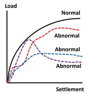
Figure 3 shows some examples of load-settlement curves of piles with anomalies compared to a pile expected to perform normally. The red curve is abnormal because of kinks in the curve, possibly resulting from pile defects or unexpected ground conditions that cause the pile to settle abruptly when loaded. This inability to sustain load at localized portions of the curve is not acceptable. The purple curve shows normalcy up to a point and degrades abruptly, finding a plateau with a lower load and increasing settlement. This might occur if the pile base is poor or suddenly loses support coupled with a loss of a portion of shaft friction or deterioration of shaft friction. One example is a case of cavities, archetypal in limestone areas. Lastly, the blue curve is abnormal due to its inability to reach the expected design load and experiences excessive settlement too early. This might occur for a pile that has fully maximized the shaft friction and cannot develop the end-bearing, resulting in a “plunging” type of failure.
Case Study
A 31.5-inch-diameter (800mm) bored pile was installed to a depth of 85.3 feet (26m) below ground in alluvial soil. These soils were formed by transported material deposited and cemented over time. The working load for such a pile is 450 tons (4000 kN). Please note that pile capacities provided by geotechnical engineers are always stated as allowable loads (ASD) or working loads, typically with a safety factor of two against a geotechnical failure.
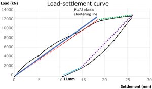
Figure 4 shows the load-settlement curve for an instrumented preliminary pile test carried out for the 31.5-inch-diameter (800mm) bored pile. The pile was loaded to 3 times the working load so the full value for shaft friction could be developed. During the application of the lower range loads (red line), the curve is approximately linear and somewhat elastic. This means that the pile is behaving well, and the response has not reached a state of yielding. When loads are higher (green line), it can be seen that the gradient of the curve has decreased, meaning stiffness has degraded. This behavior is analogous to materials approaching yield when a higher load range increases settlement. After reaching 3 times the design working load, the pile was unloaded (purple line). The unloading line usually has a steeper gradient because the pile loading process stiffens the soil around the pile. Lastly, the final portion of unloading to zero load (blue line) shows a very slight stiffness reduction similar to reaching yield during the loading process. However, this may not be obvious or observed in all tests.
After unloading, it is helpful to examine the residual settlement (0.43 inches [11mm] in Figure 4). This is the settlement that is permanent and cannot be recovered. A high value of residual settlement usually means that the pile has been loaded beyond yield, resulting in large permanent deformation. Conversely, a lightly loaded pile with its load-settlement path running along the linear-elastic portion of the curve will likely return to zero load with minimal residual settlement.
Sometimes it can be helpful to compare the gradient of the load-settlement curve against the elastic shortening gradient (PL/AE line). For example, the elastic shortening of a bored pile without any confinement is given by PL/AE, where P is the applied load, L is the length of pile, A is the cross-sectional area, and E is Young’s Modulus.
The load-settlement gradient of a friction pile should generally be similar or even very slightly steeper compared to the elastic shortening gradient. This is because of the presence of soil confinement and shaft resistance. However, suppose the gradient of the load-settlement of a pile is gentler than the elastic shortening gradient. In that case, it may be a case of less friction being developed (e.g., softer soils) along the shaft or a case of stiffer soils located only at the lower end of the pile.
Calculation of Pile Settlement
There are various methods to estimate anticipated pile settlement in design. One of the easiest ways to calculate pile settlement by hand is by Vesic (1977), as shown in Figure 5. In this method, the pile head settlement is the sum of three components, namely axial compression (ws), the settlement at pile toe due to shaft load (wps), and settlement at pile toe due to end-bearing load (wpp).
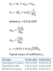
Axial compression in soil can be simplified by assuming it as 75% of unconfined elastic shortening (PL/AE). The formula given by Vesic uses the sum of end-bearing load and a fraction (0.5 to 0.67) of shaft friction load in place of axial load in the unconfined elastic shortening formula to calculate the axial shortening of the pile in soil. Settlements due to shaft load and end-bearing load are given by the ratio of shaft design working load (Qs) and end-bearing design working load (Qb) against the ultimate bearing capacity at the pile toe (Qo), normalized by the relevant dimension (pile length L and pile diameter d, respectively) and multiplied by Cp and Cs, empirical coefficients subject to variability. Because of this, it is appropriate to study the sensitivity to this variability during the design process and benchmark against past experience in similar ground for similar piles before relying too much on the result.
What is important to note in using this method is that the value of settlement calculated is highly dependent on what value of Cp is selected and the value of ultimate base capacity qo. The method recognizes that sand normally has a higher ultimate bearing capacity than clay. For example, the limit on end-bearing can be 40,000 kPa compared to 15,000 kPa for sand and clay, respectively. Therefore, the Cp value for clay is correspondingly lower compared to sand.
It can be noted that most pile settlement comes from axial compression and base settlement. Because of this, designers who need to control settlement might want to consider increasing pile stiffness (e.g., higher grade concrete and increased steel reinforcement area) and improving the pile toe condition (e.g., base grouting). Another strategy is to design the pile as a pure friction pile (i.e., there is no reliance on end-bearing to achieve the pile capacity). In such an instance, it is possible to reduce the overall safety factor on shaft friction to 1.3.
From Figure 6, it can be observed that the pile settlement at working load is approximately equal to the unconfined elastic compression (i.e., PL/AE). This can be a very crude approximation to estimate pile settlement without any further computation. However, for a friction-only pile, the settlement should be halved. This assumes the settlement due to shaft load is small and there is zero settlement due to end-bearing load. Thus, the only component left is the axial pile compression which reduces to about 0.5PL/AE, according to Vesic’s equation.
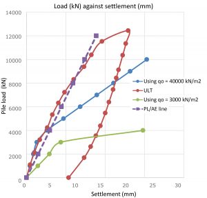
Figure 6 shows a comparison of the load settlement curve predicted using Vesic’s equation against data from an ultimate load test for the same 31.5-inch-diameter (800mm) bored pile with a working load of 4,000 kN. It can be seen that the Vesic equation predicted the pile settlement quite well (by assuming qo = 40,000 kN/m2), but only up to the working load of 4,000 kN (at about 0.2-inch [5mm] settlement).
Beyond that, the predicted settlement is much higher than the actual settlement. The reason for this is the conservative assumption of maximum shaft friction. Using Vesic’s equation, once the maximum shaft friction is reached, the rest of the load would be taken by increasing end-bearing, which comes at the expense of a much higher settlement. For loads up to the working load, as the design of the pile has already taken into consideration developing very little end-bearing and mainly relying on shaft friction, Vesic’s equation predicts settlement quite accurately, as seen in this example, when using an artificially high qo to minimize the contribution from component wpp.
However, when using a value of qo = 3,000 kN/m2, which is the actual value used in the pile design, Vesic’s equation over-predicts settlement significantly. Therefore, designers need to be cautioned on the sensitivity of qo and notice that qo may also vary due to size effects. This illustration is not meant to be an attempt to validate or invalidate Vesic’s equation for any case. Designers still need to consider the design assumptions, ground conditions, past experience, sensitivity, etc., when calibrating this equation for use in a new situation.
Other Points to Note
In loading a test pile, a kentledge reaction system (stacking up concrete blocks or steel plates as a counterweight) is customarily used. However, the process is slow, requires significant space, and is not practical for very high loadings. Nonetheless, many designers prefer this method due to the easy interpretation of test results. The stacking of high loads on a small area requires the ground bearing capacity to be checked. There have been instances of kentledge collapses due to inadequate bearing capacity. Sometimes, it is not practical to test a large diameter pile due to the high loads. Some codes (e.g., Eurocode 7-EC7) allow results of a pile load test to be extrapolated for a pile diameter not exceeding 2 times.
Conclusion
For buildings with high column loads, bored piles are often adopted. However, due to the customary practice and compliance with regulatory requirements, pile load tests are almost always required. The provision of pile load tests allows the designer to verify design parameters, design more economical piles, check the quality of materials and workmanship, and ultimately show that the performance meets load-settlement requirements.
It is important to understand the difference in development rate for shaft friction and end-bearing. The load-settlement curve is an important plot to assist designers in understanding the pile behavior.
Pile settlement can be easily calculated using Vesic’s equations but, just like any settlement calculations, the value cannot be taken to be precise. It is only a means to offer insights to the designer as a basis for comparison when carrying out a pile load test. It is essential to scrutinize the load-displacement curve of a pile-load test to be satisfied that the behavior is within expectation.■
References
ACI-318-14, Building Code Requirements for Structural Concrete and Commentary
ACI-336.3R-94, Design and Construction of Drilled Piers
Singapore Standard SS CP4:2003, “Code of Practice for Foundation,” SPRING Singapore, ISBN 9971-67-914-0
Eurocode EN 1992-1-1:2004, Design of Concrete Structures. General rules and rules for buildings (commonly known as Eurocode 2 or EC2)
Eurocode EN 1997-1, Geotechnical Design – General Rules (commonly known as Eurocode 7 or EC7)
Eurocode EN 1536:2010, Execution of Special Geotechnical Works – Bored Piles
Vesic, A. S. (1977) Design of Pile Foundations, National Cooperative Highway Research Program, Synthesis of Practice No. 42, Transportation Research Board, Washington D.C.