
Cross-Laminated Timber (CLT) panels are commonly used in mass timber structures. As with any structural element, proper detailing of the connections is crucial. Structures with practical connection details are usually cost-efficient and easy to fabricate and assemble. In contrast, poorly conceived connection details often result in an overly costly structure plagued with difficulty.
There is little guidance currently available on detailing CLT connections, although the CLT Handbook provides some guidance. It is not unusual for engineers with limited experience designing timber structures to rely heavily on exposed steel hardware to make CLT connections. Exposed hardware is not only visually undesirable but also performs poorly in a fire, making it unsuitable for a structure that is required to have a fire-resistance rating. It is not difficult to detail CLT connections with little more than screw heads exposed.
Self-drilling structural screws are the most common and versatile fastener for CLT connections. They are proprietary products, and their structural properties are usually documented in the manufacturer’s technical literature and product evaluation reports. Be cautious using products that do not have North American product evaluation reports. Since some screws are manufactured in Europe, it sometimes requires an interpreter to decipher the technical literature, which may cause an inaccurate interpretation. When only ultimate strength values are provided, it is customary to use a factor of safety of 3.0 to establish allowable strength values. Still, values as high as 5.0 have been used for certain seismic applications.
Exercise caution using long, fully threaded screws, which can restrain timber volume change associated with fluctuations in moisture content. Such restraint can result in the splitting of timbers or rupture of the fastener.
In detailing CLT connections, consideration should be given to the ease of fabrication. There are a variety of Computer Numerical Control (CNC) machines used to fabricate CLT panels, and each has its limitations. Some machines can only make cuts from one side of the panel, and thus the panel must be flipped over in the plant to make cuts on the opposite side. Consequently, it is more cost-effective to use connection details that allow all cuts to be made from the top side. For instance, an internal spline joint is more straightforward to fabricate than a tongue-and-groove joint. It is also efficient to be able to rout grooves or rabbets on the edge of a long CLT billet before it is cut into individual pieces. So, it makes sense to have consistent panel edge details.
CLT connections should be detailed in a manner that allows any qualified CLT supplier to bid on the project. If a particular supplier has been selected for a project, it is wise to consult with them on what connection types they can execute most efficiently.
Floor and Roof Panel Connections
The most common and versatile edge connection for a floor or roof panel is the surface spline joint (Figure 1). A shallow rabbet is routed in the top of each mating panel, and a narrow plywood strip is nailed across the joint in the field. Nails are typically used rather than screws, except when they are loaded in pullout.
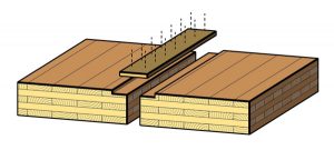
The plywood splines are typically ¾-inch to 7⁄8-inch-thick and approximately 6 inches wide (splines can be up to 10 inches wide when an aggressive nailing pattern is required). The diaphragm strength is controlled by the spline thickness and nailing pattern since the CLT panels are substantially stiffer and stronger than the splines.
Where the floor or roof is part of a fire-rated assembly, it is essential that the panels fit tightly. Fire-stopping sealant should be used where there is a gap unless there is a concrete topping over the panels.
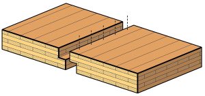
The half-lap joint (Figure 2) is also commonly used to join CLT panels. The joint is secured with screws. The half-lap joint is more costly to fabricate than a surface spline joint, and it reduces the effective width of the panels slightly. It has the benefit of being able to transfer modest loads across the joint.
An example of an application where a half-lap joint would be appropriate is adjacent to a cantilever where the joint must resist uplift. If the load at the joint is substantial, there could be a tendency for the panel to split, and reinforcing screws should be considered.
Bearing Wall Connections
CLT bearing walls supporting CLT floor and roof panels are well suited to multi-family residential projects. Platform framing is common for low and mid-rise buildings. The simplest platform detail is a butt joint (Figure 3).
The butt joint requires minimal fabrication effort since the panels are merely square cut. However, it is an inefficient joint to erect since the positioning of the panels can be tedious and consumes crane time. The butt joint also requires a large number of toe screws or exposed steel angle connectors.
A cleated joint (Figure 4) is more practical than a butt joint. A 2x cleat ripped to a width equal to the space between the face plies of the wall panel is used to position the upper wall panel and provide a point of attachment. The joint is assembled with short screws, and no extraneous hardware is required.
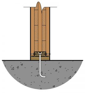
The connection to the foundation also utilizes a 2x cleat (Figure 5). The bottom of the CLT wall panel should never be allowed to come in direct contact with the concrete foundations and should bear on a pressure-treated sill.
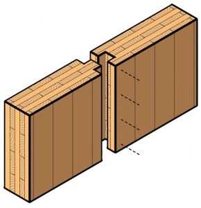
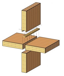
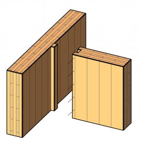
Joints between panels are commonly either half-lap joints or tongue-and-groove joints (Figure 6). Both a half-lap joint and a tongue must be cut from both faces of the panel. This reduces the effective width of the panel.
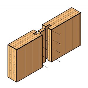
An internal spline joint (Figure 7) is a practical alternative to the tongue-and-groove. The groove in the edge of the panel can be cut without needing to flip the panel over in the shop, and there is no reduction in effective panel width. A 1¾ x 5½ LVL is a good choice for a spline.
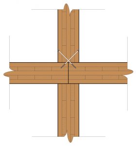
Butt joints are often used at wall corners and intersections. Although simple to fabricate, butt joints tend not to fit tightly and can open up when panels season and shrink. Very small gaps can become problematic and can result in a breach of an acoustic or fire-resistant barrier.
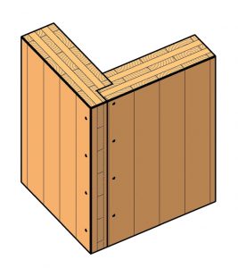
A rabbeted corner joint (Figure 8) with half-laps cut in the edge of each panel is more practical than a butt joint. It results in a neater joint that tends to stay tight. A cleated joint (Figure 9) is a smarter choice than a butt joint where wall panels intersect.
Connection Design Responsibility
It is customary for the Structural Engineer of Record (SER) to be responsible for the design and detailing of mass timber connections. This is different from what is common practice for structural steel or glulam timber structures, where the SER indicates reactions or member forces and delegates connection design to the fabricator.
Engineers who lack experience designing mass timber connections should require the mass timber contractor to engage a qualified timber specialty engineer to provide those services.■
This article originally ran in the Timber Frame Engineering Council (TFEC) Timber Design Guide 2019-15. It is reprinted with permission. TFEC documents are available at www.timberframeengineeringcouncil.org.