
Located at 301 Mission Street, the 650-foot-tall Millennium Tower was designed to be San Francisco’s premier residential address. The project geotechnical report predicted 4 to 6 inches of settlement over the project’s life; however, as construction neared completion in 2009, the settlement had already reached 10 inches. As development occurred on adjacent parcels, accompanied by continuous dewatering of the surrounding soils, settlement continued. By 2014, instrumentation installed to monitor the effect of adjacent construction recorded that the mat had dished, settled nearly 14 inches and that the roof had tilted to the northwest a similar amount. As the City of San Francisco threatened to red tag the building, counsel for the developer, Mission Street Development (MSD), retained Simpson Gumpertz & Heger (SGH) to determine if the settlement had damaged the structure and created a safety issue. Although SGH found that settlement had not appreciably affected the structure’s adequacy, in 2015, with settlement exceeding 16 inches, litigation ensued between the homeowners’ association, MSD, the City of San Francisco, and the development teams for adjacent projects. Under the terms of a negotiated settlement, SGH designed a foundation stabilization upgrade that formed the basis for dispute resolution and is currently under construction. This article focuses on the structural aspects of the problem and the upgrade.
Structure Description
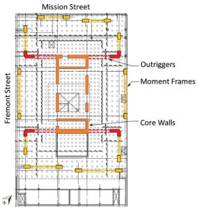
The 58-story tower, with a single basement, was constructed together with a structurally separate but functionally interconnected 12-story structure atop a 5-story subterranean garage. Tower floors comprise post-tensioned concrete flat plates supported by a central reinforced concrete bearing wall core and perimeter columns. The structure was prescriptively designed to the criteria of the 1997 Uniform Building Code. Seismic and wind forces are resisted by a dual system comprising special reinforced concrete shear walls at the building core and special reinforced concrete moment resisting frames at the building perimeter. Plan dimensions are approximately 100 feet east to west by 150 feet north to south (Figure 1). Six levels of outriggers, consisting of extensions of the north and south core walls to the perimeter moment frames, assist the core in resisting east-west overturning forces.
The foundation is conventional to San Francisco high-rises comprising a 10-foot-thick, heavily reinforced concrete mat supported by approximately 940 precast, prestressed concrete piles driven into a dense, silty sand layer present approximately 50 to 85 feet below grade. Bedrock is more than 150 feet below the sand, with layers of clay and alluvium between the rock and sand.
Settlement Cause
Extensive geotechnical investigation and analyses were conducted, including three-dimensional modeling of the subsurface conditions and imposed loading using FLAC 3D software, a finite difference method code used by geotechnical engineers. The analyses indicated that settlement resulted from consolidation of a deep-seated clay layer under the 11 ksf imposed tower loading, combined with increased effective stresses in these materials resulting from long-term lowering of the water table for construction of this and adjacent structures. Further, the analyses suggested that, under the effects of secondary compression (creep), settlements could double over the structure’s remaining life.
Perimeter Pile Upgrade
During mediation, the homeowners insisted on a substantive retrofit that would arrest settlement and allow tilt recovery. The homeowners’ consultant proposed installing several hundred micro-piles through the existing mat, extending 250 feet and supported in bedrock, with sequential jacking of the load onto the piles to remove tilt. Unfortunately, the parties could not reach an agreement to fund the substantial estimated cost of this retrofit. As an alternate, SGH proposed underpinning the structure along its north and west sides.
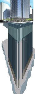
The upgrade includes the installation of 52 piles, spaced at approximately 5 feet, drilled into the underlying bedrock beneath the Fremont and Mission Street sidewalks (Figure 2). Following pile installation, an extension of the existing foundation mat is constructed around the piles, which are sleeved through and extend above the mat. Hydraulic jacks are used to transfer 800 kips of load to each pile, removing approximately 20% of the building’s weight from the original foundation and transferring this load directly to the bedrock underlying the consolidating clays. FLAC 3D analysis indicates this retrofit will effectively arrest further settlement along the structure’s north and west sides and allow gradual recovery of tilt through a modest continuing creep settlement of the east and south sides.
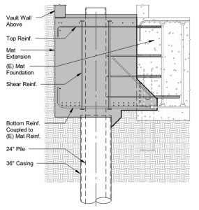
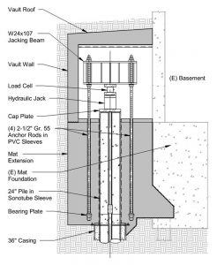
The 800-kip jacking load was based on preliminary estimates of the existing mat’s flexural and shear capacity and its ability to safely withstand large forces imposed by an external line of piles. As design progressed, SGH implemented capacity-design principles to assure the new piles would not take excessive loading that would overstress the existing mat due to continued building settlement or earthquake shaking. As illustrated in Figure 3, a shear key is excavated at the existing mat edge to expose flexural reinforcing. Mechanical couplers are used to extend the existing reinforcing into the new mat extension. Additional epoxy-adhered dowels are used to assure that the shear strength of the attachment exceeds the flexural capacity of the joint, assuring ductile behavior in the event of overload. Load is transferred to the new mat extension from the piles through hydraulic jacks placed at the top of the piles, as shown in Figure 4. These jacks push downward on the piles and upwards against a jacking beam that extends across the top of each pile and which is anchored to the mat extension with four 2½-inch diameter high-strength threaded rods at each pile. These rods are selected such that their combined yield strength limits pile load to approximately 1,100 kips, considering material overstrength and strain hardening. Detailed nonlinear finite element analyses confirm the existing mat has the capacity to resist such loading without failure, as does the interconnection of the new and existing mats. In the event of overload associated with unanticipated settlement or earthquake, pile loading is limited by fuse-like yielding of the high-strength rods. The hydraulic jacks have mechanical lock-off capability and can be re-energized if necessary to add or reduce pile loading. A protective vault is constructed around the pile tops and jacks to allow this, if necessary.
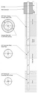
The upgrade intends to remove some loading from the consolidating clays and transfer it to the underlying bedrock. It is important that the new piles do not transfer load back to the soils above the clay or the clay itself. Figure 5 illustrates the pile design, which consists of a concrete-filled 24-inch-diameter steel casing, with a single, central, 103 mm hollow, high strength, coarse thread reinforcing bar, which also serves as a tremie. The pile extends into bedrock as an uncased 20-inch diameter reinforced shaft that transfers load through friction. Above the clay, the 24-inch-diameter pile is installed through a 36-inch-diameter outer casing. The annular space between the inner and outer casings is filled with a low-strength controlled-density fill only after the load is jacked onto the piles, preventing any load transfer in this region. The outer surface of the 24-inch-diameter casing is coated with a friction-reducing material to minimize load transfer directly to the clays. The penetration length into rock and the effectiveness of the friction-reducing coating will be confirmed with an indicator pile, to be tested using Osterberg Cells within the 20-inch-diameter portion of the shaft. The indicator pile will also incorporate several sets of discrete strain gauges and continuous fiber-optic strain measurement.
The upgrade was submitted for permitting as a voluntary seismic upgrade under the San Francisco Existing Buildings Code provisions. This code permits voluntary upgrades of any type, providing the design team can demonstrate that the upgrade will not reduce the building’s safety, impose more load on existing elements than they can withstand, or create a structural irregularity. SGH conducted extensive nonlinear dynamic analyses using PERFORM 3D software to confirm the project complies with these requirements and demonstrate that the building can meet typical performance criteria for new structures. In addition, a city-appointed team of two structural and two geotechnical engineers performed an independent design review.
Construction and Beyond
Construction was initiated in October 2020, with completion scheduled for October 2022. The new piles will be loaded by stressing the hydraulic jacks at all piles simultaneously, in 100 kip increments, with a hold of 24 hours after each load increment to allow monitoring of building response. Following loading, the pressures will be maintained for 1 month while additional monitoring occurs. The design team anticipates, based on analysis, that some substantial rebound of the existing piles will occur as they are unloaded, resulting in loss of effective load in the new piles. If this occurs, the piles will be reloaded to the design level before completing the vault and demobilization from the site.
Continuous monitoring of the project will occur for 10 years following construction completion. Monitoring instrumentation includes load cells at each pile, settlement markers on the mat, piezometers and extensometers in boreholes at depth, and survey points on each of the building’s facades and roof. As noted previously, the jacking load can be adjusted as needed to influence the building’s behavior.
Conclusions
The Millennium Tower’s settlement and tilting did not pose a safety issue but created unacceptable devaluation of the homeowners’ investments, especially after national news media publicized the problem. SGH’s upgrade design employed conventional underpinning technologies to arrest the settlement, remarkable only for the scale of the project, the public scrutiny that occurred, and the sophisticated analyses the team of structural and geotechnical engineers employed to substantiate the design.
Since the Millennium Tower settlement problems emerged, design practice in San Francisco has changed substantially. For example, all high-rise buildings developed since 2009 have used deep foundations extending to rock. Furthermore, the City of San Francisco has instituted administrative procedures requiring independent geotechnical review of all buildings exceeding 240 feet in height.■
See the Geotechnical Issues article for additional information on the geotechnical aspects of the Millennium Tower.