
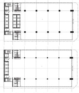
The latest addition to North Sydney’s growing business district is 100 Mount Street. The design of the building by SOM and Architectus takes advantage of panoramic views of Sydney Harbour with an integrated approach to architecture and structural engineering. Tenant views are maximized with an offset core and 20-foot column-free cantilevered zones along the North and South face of the building. The offset core is balanced by an innovative composite mega-bracing system which also creates the architectural identity of the project. The building’s state-of-the-art structure was engineered by SOM and Enstruct, the engineer of record. Refer to Figure 1 for typical floor plans.
The project was developed by Dexus and Laing O’Rourke, who also served as the main contractor for the project. The developer-contractor-led project sought to embed efficient and constructible solutions throughout the building. These guiding principles resulted in the exposed structural concrete core, exposed concrete, and steel mega-bracing system, and soaring closed cavity curtain wall system of the building design appropriate for the mild climate of Sydney.
Spring Street bounds the building to the North, Walker Street to the East, Mount Street to the South, and neighboring 80 Mount Street to the West. The design response to the site was to locate the building core immediately adjacent to 80 Mount Street, providing unobstructed views and street access in the remaining three directions. The offset core design of the building enhances the tenant experience and connection to the urban environment and poses a structural challenge under wind loading. Seismic activity is not significant in this region and is not a controlling design condition for buildings with regular proportions.
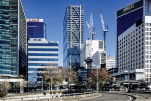
North Sydney is situated atop a sandstone plateau over the harbor, approximately 300 feet above sea level. The natural rise in elevation creates an escarpment, a terrain condition that increases wind speeds at the elevated site. This factor, combined with the relatively taller 100 Mount Street compared to surrounding buildings, caused an increase in wind loads as discovered by wind tunnel testing. The offset core design would have led to objectionable torsional building movements if left unchecked. This design challenge led to the inclusion of the exposed mega-bracing system, which balances the offset core and allows the architectural intent of the building to be achieved. Refer to Figure 2 for a construction photograph of the main building systems and immediate building surroundings.

The typical floors are framed with bonded post-tensioned concrete band beams and floor decks. The wide/shallow band beams are spaced at 30 feet on-center and span 55 feet to concrete columns and cantilever 20 feet beyond for unobstructed harbor views. The band beams are notched at inflection points for routing of building services, an integrated solution that allows the typical floor-to-floor height of the building to be 13 feet 4 inches. The typical framing is supported by just 10 vertical high-strength 14,000 psi concrete columns. The offset concrete core to the West both supports the floors and provides resistance to lateral loading. The design of the core includes elevator cabs that open directly into the floor plates. The core design allows the interior floor area to be captured as leasable tenant space as elevator banks drop off higher up in the building. This approach is highly efficient from a leasing perspective but results in a core with marginal torsional resistance. An efficient core structure required a supplementary lateral system on the East face of the building to balance the inherent torsion and potential movements from eccentric wind loads. The supplementary lateral system also minimized the potential for wind uplift and deep tie-down foundations below the core, which were problematic due to a future tunnel easement near the site.
The supplementary lateral load resisting system required high lateral stiffness to balance eccentric wind loading and possible uplift on the core. Mega-bracing of the Eastern concrete columns was selected over a moment frame with tightly spaced columns because of the high stiffness requirements and to minimize obstructions to valuable harbor views. Structural steel was chosen as the bracing material to minimize brace sizes and simplify erection and other construction issues. Steel mega-bracing of the concrete columns forms a composite bracing system, adding design complexity from concrete creep and shrinkage and thermal effects.
The mega-bracing was initially proposed to be a chevron pattern or “k-bracing” to mitigate the effects of the composite system. The initial bracing configuration is less stiff than an “x-bracing” and also has longer unbraced diagonals which would increase steel tonnages. The design team explored alternative bracing patterns and relied upon internal research and typology optimization to select the final pattern – an x-braced frame with a raised central node. The most efficient bracing pattern is an x-brace with the central node located at 3⁄4 of the bracing module height. The bracing at 100 Mount Street is located at the 2⁄3rd module point to align with a floor level and is approximately 10% stiffer than an x-brace. This system was selected to maximize the supplementary support offered to the core. Refer to Figure 3 for an elevation photograph showing the x-bracing with central node at the 2⁄3rd point.
The mega-bracing geometry is highly efficient in achieving the engineering goals but could resist long-term creep and shrinkage movements of the concrete columns. However, this self-stressing behavior causes compression loading in the braces, increasing the demands on the bracing by approximately 250% compared to required wind loads. Designing for these increased loads would be inefficient in material consumption and increase brace member sizes which block valuable harbor views. Alternatively, the design team developed a central node connection with an internal sliding mechanism that resists the necessary wind loads but relieves the creep and shrinkage strains.
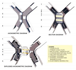
The concealed central sliding node consists of steel finger plates and brackets sandwiching elastomeric bearing pads. Elastomeric bearings are a common structural engineering component that provides vertical support while allowing lateral movement, most common in bridge structures or expansion joints in buildings. The sliding movement is accommodated by the low shear stiffness of rubber components within the bearings while maintaining vertical contact and support between elements. The central sliding node sandwiches elastomeric bearing pads between steel bearing brackets to resist wind load reversals through compression, either in the top or bottom bearing assembly. The size of the bearings and gap between steel node elements were designed to accommodate movements from elastic column shortening, long-term creep and shrinkage, floor post-tensioning, differential thermal movements, and other effects. The bearings can be observed in service with removable closure plates and replaced if necessary. The result of the design is a concealed node that minimizes loading and resulting sizes of the steel bracing. Refer to Figure 4 for a diagram of the concealed central sliding node and Figure 5 for a photograph of the final bracing design and architectural appearance.

100 Mount Street is a project built on efficiencies, from the core design and floor leasing to engineering systems and constructability. The building’s architectural design embraces efficient design and proudly displays the composite mega-bracing as the defining architectural feature of the building. These achievements were made possible by the close collaboration of the design and construction teams striving toward a successful project that embodies state-of-the-art building systems while enhancing the tenant experience and urban environment.■