
Three-dimensional (3-D) volumetric construction is also known as concrete modular construction or Prefabricated Prefinished Volumetric Construction (PPVC). This construction method involves the stacking of rectangular factory-finished modular components on-site to form a complete building, similar to Lego® bricks. Joints are typically grouted with special interfacing details. To achieve speed and high productivity, the components have to be substantially completed with minimal site work. This article looks at some of the key design considerations and strategies that designers need to think about when using this type of construction method.
Overview
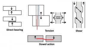
3-D volumetric construction (3DVC) evolved from traditional precast concrete construction where precast components in two dimensions were assembled on site. Traditional precast concrete construction typically consists of slabs, beams, columns, and wall components connected on-site via bearing, tension, or shear joints (Figure 1). Moment joints are less common. Connection strategies may involve using a corbel, half-joints, or open pockets for in-situ grouting with placed-on-site reinforcement bars. An opening in a structural element may be formed by pipes allowing room for lapping of reinforcement bars; the remaining voids can then be grouted with high strength grout. Other connecting joints may consist of steel plates with simple on-site bolting. Shear resistance at interfaces may be achieve using corrugated or roughened concrete surfaces (acting as a shear key) or C-shaped links with cottering bars (using reinforcement bar dowel action). To resist tension forces, the use of high-strength steel wires can be an effective solution.
When precast slabs, beams, columns, and walls are assembled in the factory, instead of on-site, this becomes 3-D modular concrete construction. Considerably more effort is required to produce a 3-D component in a factory. The builder needs to be aware that this 3-D component is also larger and heavier to maneuver, hoist, store, and transport.
One advantage of using 3DVC is the increase in speed and productivity on-site, especially when time constraints are tight and labor costs are prohibitively high. Also, as the prefabrication is carried out in a factory-controlled environment, prefabricated modules can be manufactured to a higher-quality standard. To take full advantage of modular construction, the building itself must be modular and repetitive so that the number of different modules can be minimized to achieve economies of scale. Remember that portions of the structure which cannot be modularized will have to be cast in situ, on-site. It is not uncommon to see 3DVC technology for high-rise residential projects where there are a large number of repetitive residential units, such as condominiums and apartment flats. The bedrooms and living rooms of such residential units are typically standard within the same stack and with minimal variations across the stacks. Also, residential developments require much less MEP (mechanical, electrical, and plumbing) input compared to other building types, making it favorable for minimizing connecting works across the modules.
Typical Modular Units
A typical high-rise residential tower block is shown in Figure 2. Each residential unit can be compartmentalized into several rectangular box modules. Each bedroom is typically one module. The living room modules might be larger and sometimes integrated with a kitchen or a cantilevered balcony. There will still be areas on a floor plate which require in-situ casting work, such as the elevator lobby and corridor access into the dwelling units.
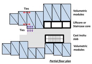
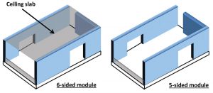
Figure 3 shows some typical five-sided or six-sided 3DVC modules. The six-sided modules have the advantage of a working platform in the form of a ceiling slab, adding to its rigidity as a complete and fully enclosed box. However, the double slab (ceiling and floor) at every level will consume valuable headroom and the dead space between slab is wasted. Therefore, five sided modules are often preferred (i.e., without ceiling slab). However, temporary rigidity, especially in torsion, needs to be considered and a temporary working platform needs to be provided for workers working on top of the module during installation.
In modern concrete construction for residential homes, beams are not preferred for aesthetic reasons. The presence of beams would allow kinks (i.e., beam profile) to be visible at the wall and ceiling slab interface, especially where false ceilings are not constructed. Therefore, the strategy would be to design one-way spanning slabs to be supported by walls and omit the beams. In residential units, as the span of slabs are typically 9.8 to 13 feet (3-4 meters), it is possible to have relatively thin slabs of approximately 6 inches (150mm) for slabs supported by walls. In areas where beam support is unavoidable, hidden beams (i.e., localised strengthened strip of slab) or band beams (i.e., shallow and wide beams) are introduced. Similarly, columns are not a preferred option for the same reason and long slim walls are often used in place of columns for residential construction.
Therefore, it is sensible to design a box 3DVC module using only structural walls and slabs, without the need for beams and columns. The walls need to be strategically located to avoid coinciding with openings required for doors and windows, and they can be designed to a suitable length to meet strength and stiffness requirements. Non-structural walls can be used to fill up remaining voids to compartmentalise spaces. Walls are made as thin as possible to reduce overall weight but also need to cater to fire resistance and slenderness considerations.
Transfer Deck
A transfer deck is a transfer slab required to support the walls and columns above it with walls and columns below it which are not aligned, such as in the case of a basement garage located below a tower block. In addition, there may be instances of requiring large drops in the slab structure, such as accommodating planting boxes or swimming pools. The transfer slab needs to be designed for moment, shear, and punching shear arising from usually high loadings from the superstructure, in addition to meeting deflection requirements. To provide for large drops, a double slab may be useful. A double slab transfer deck (box deck) may achieve significant savings, especially if regions of low loading demands are hollowed out, instead of casting a massive block of concrete, which adds to dead weight. The transfer deck also acts as a launching platform for the commencement of modular stacking of the volumetric units.
Analysis and Design
The structural analysis for modular construction is not too different from that of a conventional reinforced concrete building. The building must satisfy strength and stiffness requirements in accordance with the applicable design code. For serviceability, the building cannot crack, deflect, or vibrate excessively to an extent noticeable and alarm the user. The building aspect ratio (e.g., height/breadth greater than 7 might be considered slender) and structural element sizes need to be adequate to address these concerns.
However, there are several peculiar issues associated with modular construction that designers need to be aware of. One, diaphragm action is often assumed for a cast-in-place concrete slab. Besides resisting vertical gravity loads, slabs play an important role in transmitting the lateral loads to the vertical structural elements such as walls and columns, using diaphragm action. Therefore, it is important to ensure that slabs between modules are tied together adequately so that they act integrally and do not fragment under load. Tie reinforcement between slabs of abutting volumetric modules must be able to take the minimum tying force specified by the relevant codes.
Next is the treatment of abutting walls. Should the twin wall configuration be modelled individually or as a composite wall? The answer will depend on how the vertical joint connection is being designed and detailed. For simplicity, it is easier to model them as individual walls with ties at appropriate discrete locations. Normally, the design force to tie the two walls will not be excessively large. High-strength non-shrink grout filling the voids between the abutting walls will primarily act as a void-filler and not be required to ensure composite action. If the twin walls were designed as a composite wall, then the connection details would need to ensure adequate shear transfer in the vertical and horizontal directions.
Thirdly, the volumetric units must be able to resist forces induced during the hoisting operation when supported at the lifting points as well as any other temporary condition during transportation, handling, and storage. Lifting hooks should be planned such that they have sufficient development length and produce uniform load distribution. In addition, the module should be stable and not tilt during hoisting. It is also good practice to use a steel lifting frame to lift the modules, instead of inclined wires which would introduce inclined forces into the module. If necessary, additional temporary supports may need to be introduced during the lifting operation.
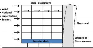
Lateral loads for a high-rise building may typically be comprised of wind, notional, imperfection, and seismic loads (Figure 4). For a tall building, the wind load may be critical, especially in areas where wind speeds are high. Imperfection loads are lateral loads imposed due to the out-of-plumb of vertical members (i.e., 1/200 for Eurocodes) or geometric imperfections. In the legacy British Standards, reinforced concrete structures must withstand a minimum notional load of 1.5% of dead load to account for imperfections.
For seismic regions, there are specific requirements on horizontal diaphragms and shear walls. First, the designer needs to consider whether floor diaphragms are topped or untopped, as there are restrictions on the use of untopped diaphragms. Next, the American Concrete Institute’s ACI 318 Building Code Requirements for Structural Concrete and Commentary, also has specific requirements for using friction coefficient μ = 1 when relying on shear friction. Similarly, for shear walls, there are provisions to allow yielding only at the steel and to achieve satisfactory post-yield performance. Localized regions in the diaphragm and shear walls might require additional strengthening, such as at the edges and offsets. As such, it might not be easy for volumetric construction to comply with the onerous requirements required at highly seismic regions.
Connections
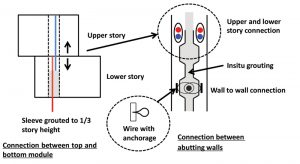
The connections of a volumetric construction are the most critical factors in determining the success or failure of the project. There are primarily three types of connection: the wall-to-wall connections between abutting modules (vertical joint type) and between upper and lower modules (horizontal joint type) (Figure 5) and the slab-to-slab connection (horizontal joint type) at the floor level (Figure 6).
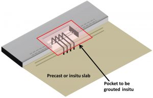
Slab joints are designed to take tension to meet the minimum tying force, ensuring integral diaphragm action to prevent fragmentation. A pocket is deliberately left opened at the slab edge which interfaces with an adjacent slab. Linking C-shaped reinforcement bars are then placed in situ to stitch across the two slabs with cottering bars, ensuring adequate anchorage. The joint is then cast with high-strength grout. It is important to note that a rigid floor diaphragm needs to be tied internally in two orthogonal directions and externally at the peripheral of the building.
Vertical wall-to-wall joints will take nominal tying force if the walls are designed as individual, separate walls. The outer wall surface which faces an adjacent wall from the abutting module would typically be roughened and corrugated. This enhances the shear transfer, even if such shear transfer is not required by design. High strength wire ropes from both modules overlap with an additional reinforcement bar inserted into the loop. The void is then filled with high strength grout.
Horizontal wall-to-wall connection will be required to take tension resulting from lateral forces causing overall overturning moments. The tension is taken by reinforcement bars which extend from the lower module to the upper module with adequate development length. These reinforcement bars are inserted in oval-shaped (preferred over circular) corrugated pipes which run throughout the height of the wall. Grouting is carried from floor level to two-thirds of the story height (e.g., approximately 6.6 feet or about 2 meters). This is to facilitate the insertion of the next level reinforcement bars which can extend into one-third of the ungrouted story height. This would also ensure continuity of vertical ties along the walls throughout the entire height of the building superstructure.
Other Issues
One of the key concerns in volumetric construction is the seepage of water through the joints. It is important to ensure that the volumetric modules are manufactured to high precision with strict control on tolerances. This is so that gaps between modules are consistent and do not exceed design specifications. At the outermost interface, a sealant will need to be applied. Beneath the sealant, a soft compressible backer rod (approximately 1.2 inches or about 30mm) is placed. This compressed backer rod, when uncompressed, should be larger than the gap. When modules are abutting and cause the backer rod to compress, it should snugly plug the gap between adjacent modules. In addition, the joint can be detailed such that a small kerb prevents direct water ingress.
Conclusion
Three-dimensional (3-D) volumetric construction is a viable construction method in urban contexts, especially when speed and productivity are key concerns. Besides dealing with the technical considerations, designers should examine the merits of each project to assess whether adopting volumetric construction can achieve economies of scale and is worth the effort. Initially, there would be a learning curve during the installation of the first few batches of modules. When the installation team is well-versed with the sequence of work, the installation would gain efficiency and speed.
The project team, including the design engineer, when applying for building approval, would need to convince the local building authority (Authority Having Jurisdiction, AHJ) on the safety and viability of any newly proposed volumetric construction system, including compliance with relevant codes. A design based on sound engineering principles with a proven track record of successfully implemented methods or systems would be helpful in giving confidence to authorities when proposing a new volumetric construction solution for a project.■