
Spoiler Alert!
The next edition of the Aluminum Association’s Aluminum Design Manual (ADM) became available in January 2020 (Figure 1). Updated every five years, the Manual includes the Specification for Aluminum Structures which provides for allowable strength and load and resistance factor design of aluminum structures, members, and connections. Because compliance with this Specification is required by the International Building Code (IBC), changes to the Specification directly affect most building applications of aluminum in the United States. Furthermore, the Specification’s provisions are used by other code organizations, such as the American Welding Society (AWS) and the American Association of State Highway and Transportation Officials (AASHTO) in their standards for aluminum structures. This article reviews the significant changes to the Specification as compared to the 2015 edition.
Figure 1. The 2020 Aluminum Design Manual.
The ADM was first published in 1994 but was preceded by several Aluminum Association publications dating back to the 1960s, including the Specification for Aluminum Structures, which celebrated its 50th anniversary in 2017. The Specification was reorganized in 2010 so that its presentation was consistent with the AISC Specification for Structural Steel Buildings. This format, which has been retained in the 2015 and 2020 editions, is presented as a unified specification that provides nominal strengths for use in both the allowable strength design (ASD) and load and resistance factor design (LRFD) methods. It is organized into chapters and appendices that are consistent with AISC’s topics; for example, Chapter D addresses members in axial tension, and Chapter E addresses members in axial compression.
Welded Strengths
Aluminum alloys are strengthened by tempering, which is achieved by heat treatment or cold working. The heat of welding offsets the increased strength gained by tempering, and this strength reduction zone typically extends 1 inch (25 mm) in each direction from the centerline of a weld. For welded connections, designers need to know the weld-affected tensile ultimate strength. Both the weld-affected tensile ultimate strength and the weld-affected tensile yield strength are required to design welded built-up members. Furthermore, the base metal and filler metal alloys in a weldment often differ and, consequently, the weld-affected strengths of both are needed.
While minimum weld-affected tensile ultimate strengths are provided in the American Welding Society’s D1.2 Aluminum Welding Code for base metal alloys, no strengths are established for aluminum filler metals in AWS’s specifications or codes. Consequently, accurately establishing the welded strengths needed for design in the Specification has been an ongoing effort. The 2020 Specification is the first to establish the weld-affected tensile ultimate and tensile yield strengths of both the base metals and the filler metals that are addressed by the Specification. The strength of the weld-affected zone, which includes both base metal and filler metal, is the weighted average of the strengths of the base metal and the filler metal defined by their contribution to the cross-sectional area of the weld-affected zone. The filler metal strengths given in the 2020 Specification are shown in the Table.

Table of nominal strengths of aluminum filler metals.
Because welding reduces the strength of heat-treated or cold-worked aluminum, designers sometimes seek to regain strength by post-weld heat treatments. An example is an aluminum light pole with a welded base; the base weld weakens the assembly where the maximum moment from wind loads occur. Designs utilizing post-weld heat treatments have been limited, however, because the previous Specification only provided post-weld heat-treated strengths for 6005 and 6063 alloys. The 2020 update adds the post-weld heat-treated strengths for 6005A and 6061, significantly extending the Specification’s usefulness.
Screw Chases
Perhaps the most compelling reason to use aluminum in structural applications is that it can be cost-effectively extruded, producing complex cross-sections without labor-intensive fabrication. A good example is shown in Figure 2, where a chase is provided at the top of the extrusion to receive a screw anywhere along the extrusion’s length, a detail widely used in architectural applications.
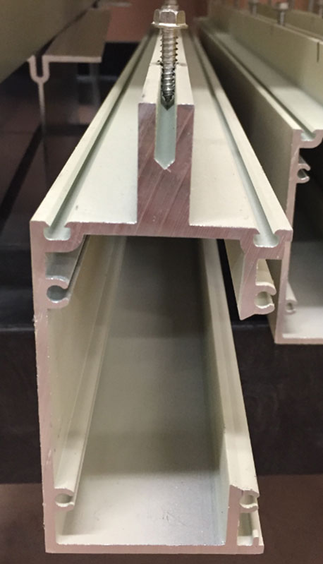
Figure 2. Extruded aluminum screw chase.
While screw chases provide economical connections for aluminum members, the pull-out strength of fasteners in the chase has not been addressed in structural design standards. The 2020 Specification is the first to include a pull-out strength for screws in screw chases, which for ¼-inch-diameter fasteners is given as:
Rn = (0.021 in2)Le Ftu (14/n)2/wc, where
Le = length of engagement of the screw’s threads in the depth of the chase (inches)
Ftu = tensile ultimate strength of the screw chase extrusion (k/in2)
n = number of threads/inch of the screw
wc = nominal width of the chase (inches)
To determine the available pull-out strength (φRn for LRFD and Rn/Ω for ASD), φ = 0.50 and Ω = 3.0.
Flexural Strength
Several changes are made to the flexural strength provisions in Chapter F.
Bending Coefficient
The equation for the bending coefficient, Cb, which accounts for the variation in the moment over the unbraced length of a beam in determining the lateral-torsional buckling strength, is changed to: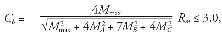
Mmax = absolute value of the maximum moment in the unbraced segment
MA = moment at the quarter-point of the unbraced segment
MB = moment at the midpoint of the unbraced segment
MC = moment at the three-quarter-point of the unbraced segment
Rm = 1.0 except for unbraced lengths of singly-symmetric members subjected to double-curvature bending from transverse loading,
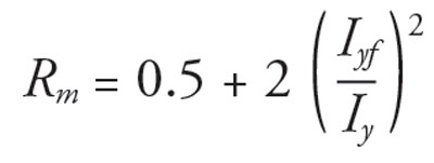
Iyf = moment of inertia of the flange on the negative side of the midheight (where the direction of the load is the positive direction) about the minor axis of the shape
Iy = minor axis moment of inertia of the shape
This equation is given in the Structural Stability Research Council’s Guide to Stability Design Criteria for Metal Structures (Wiley, 2010).
Flexure and Axial Compression
The Specification includes a direct strength method for determining the capacity of members in flexure or axial compression. This method uses the elastic buckling strength determined by the finite strip method (FSM), which is an eigenvalue analysis of a model of a member divided into strips that extend along the member’s length. The opportunity to employ such a method in design is especially important for aluminum because extruded aluminum shapes can be very intricate, which complicates the determination of their buckling strengths.
The 2015 Specification provided a method to determine a section’s flexural local buckling stress using the section’s elastic buckling stress from FSM. This elastic buckling stress was used to determine the strength of the elements of the section in uniform compression and the strength of the elements of the section in flexural compression. The strengths of the two groups of elements were then combined using a weighted average based on their section moduli. This approach was rather cumbersome because it required assigning each element of the section to either the elements in uniform compression or the elements in flexural compression, and computing the section modulus of each group. The 2020 Specification simplifies this by providing equations to use the elastic buckling stress of the shape to determine the local flexural buckling stress of the shape directly.
Single Angles
The flexural strength of single angles is revised, consistent with changes for single angles in the 2016 AISC Specification.
Block Shear Strength
The block shear strength provision in previous Specification editions was similar to an earlier AISC approach in which the strength was the lesser of yielding on the gross shear area with rupture on the net tensile area and yielding on the gross tensile area with rupture on the net shear area. In the 2020 Specification, the block shear strength is now taken as the shear rupture strength on the average of the net and gross shear areas plus the tensile rupture strength on the net tensile area. The revised strength is more accurate and less cumbersome to compute.
Flanges and Webs with Concentrated Forces
Web crippling was the only case of concentrated forces on flanges or webs addressed in previous editions of the Specification for Aluminum Structures. In the 2020 Specification, the web crippling strength for extruded shapes (Figure 3) is revised and made less conservative, and flange local bending and web local yielding are added. The strengths for these three cases are similar to those in the 2016 AISC steel Specification, as the rationale for these strengths can be equally applied to both aluminum and steel.
Figure 3. Web crippling of extruded members.
Bridges and Buildings
Around 1960, several aluminum highway bridges were built in the U.S. Consequently, and since its first appearance in 1967, the Specification for Aluminum Structures has addressed both bridges and buildings with a different set of safety factors for each. For example, while the Specification set a safety factor on tensile rupture of 1.95 for buildings, the safety factor for tensile rupture was 2.20 for bridges. In this regard, the aluminum Specification has differed from its steel counterpart, the AISC Specification for Structural Steel Buildings, which from its beginning in 1923 has addressed building structures only.
When AASHTO developed the first LRFD bridge design specifications in the 1990s, they used the Specification for Aluminum Structures as the source of the nominal strengths for aluminum structural components and established resistance factors for aluminum bridges. Consequently, when the first LRFD Specification for Aluminum Structures was published in 1994, it addressed buildings only and left load and resistance factor design of aluminum highway bridges to AASHTO.
However, allowable strength design safety factors for aluminum highway bridges lingered in the Specification for Aluminum Structures, even though allowable strength design is no longer used for bridges. The 2020 Specification drops references to bridges, thus limiting its scope to building structures, defined in the Specification as a structure of the type addressed by a building code. As with the AISC steel Specification, the aluminum Specification may reasonably be applied to all structures designed, fabricated, and erected in a manner similar to buildings, with building-like vertical and lateral load-resisting elements.
The 2026 Aluminum Design Manual
Just as the AISC has adopted a six-year cycle for revisions to the steel Specification, the Aluminum Association is considering a six-year interval between revisions to the Aluminum Design Manual. Because the IBC has a three-year revision cycle, a six-year cycle may be more suitable for standards like the Specification for Aluminum Structures that are referenced by the IBC. This also has the benefit of reducing the frequency of changes to design standards, thereby allowing design professionals to master them better.
In the next revision cycle, several issues may be considered for the aluminum Specification, including:
- The flexural and axial compression strengths of members with transverse welds that affect the full cross-section or part of the cross-section
- The flexural and axial compression strengths of members with longitudinal welds
- An unbraced length below which lateral-torsional buckling does not occur
- Provisions for tubular connections
Of course, the authors would appreciate learning of any other issues or suggestions for improving future editions of the ADM.
The 2020 Aluminum Design Manual is available from the Aluminum Association at www.aluminum.org.■