
Part 2: Seismic and Wind Drift
This article is the second of a two-part article on ASCE 7-16, Minimum Design Loads for Buildings and Other Structures, and its provisions for lateral drift determination. The first article (STRUCTURE, July 2019) discussed main points influencing seismic drift computation. In this article, the effect of soil flexibility and cracking of reinforced concrete elements on seismic drift computation of structural systems is addressed. It also discusses the determination of the level of loads for checking wind drift, return periods of wind speed maps, and allowable wind drift limits. A brief comparison between seismic drift and wind drift, in connection to their nature, and a determination procedure is covered.
Effect of Soil Flexibility Modelling
Soil flexibility can have a significant effect on the behavior of a structure. ASCE 7-16-12.7.1 (Foundation Modeling) states, “For purposes of determining seismic loads, it is permitted to consider the structure to be fixed at the base. Alternatively, where foundation flexibility is considered, it shall be in accordance with Section 12.13.3 or Chapter 19.” Therefore, structural engineers must decide the most appropriate analytical assumptions for the structure considering its construction details. The Figure illustrates four types of base restraint conditions that may be considered.
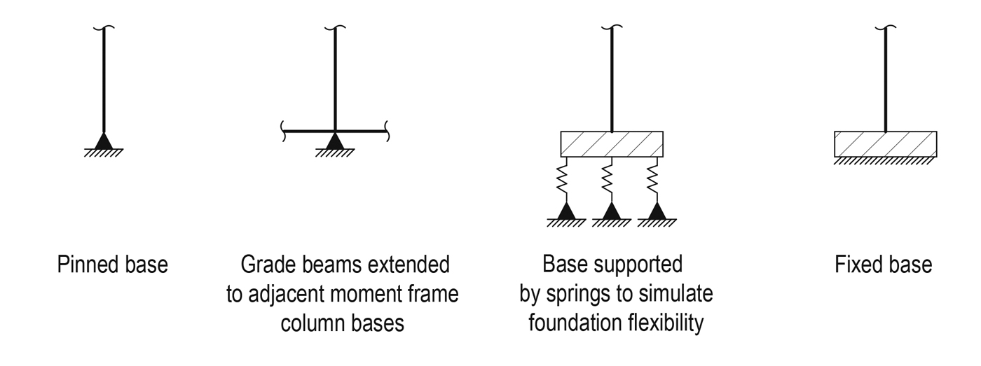
Column base restraint conditions.
Higher flexibility (pinned base) lengthens the period of the building, resulting in a smaller calculated base shear but larger calculated story drifts.
One drawback to the pinned-base condition is that the story drift of the frame, especially the story drift in the lowest story, is difficult to keep within allowable code limits. If the story drift of the structure exceeds acceptable limits, rotational restraint can be increased at the foundation by a variety of methods, as illustrated in the Figure.
Effect of Structural Elements Cracking
Seismic design is based on consideration of nonlinear response. It is, therefore, necessary to consider the reduced stiffness of seismic system elements due to cracking. ASCE 7-16 Section 12.7.3 states that, for reinforced concrete structures, stiffness properties of concrete and masonry elements shall consider the effects of cracked sections. ACI 318-14, Building Code Requirements for Structural Concrete, also states in its Commentary R18.2.2 that, for lateral displacement calculations, assuming all structural elements to be fully cracked is likely to lead to a better estimate of the possible drift than using uncracked stiffness for all members. According to ACI 318-14 – R18.2.2, the assumption of I = 0.5Ig for all structural members of the seismic resisting force system shall be permitted. It should be noted that various seismic force-resisting systems have different levels of nonlinear response, and these levels are represented by the values of response reduction factors R. The reduced stiffness of these various systems also varies based on the permitted degree of nonlinear deformation. Special moment frames, for example, may have higher stiffness reduction factors among a group of seismic force-resisting systems because this system is designed to permit a high level of nonlinear deformation.
Selecting reduction factors for different seismic systems in association with their behavior under seismic forces is not clearly stated in ACI 318-14; however, engineering judgment may be employed to select the best value for stiffness reduction based on the type of seismic lateral force resisting system and the intended level of nonlinear deformation.
Wind Load Level
Wind design has been brought into strength level design since 2010 (ASCE 7-10). As a result, many changes have been incorporated in comparison to older versions. Unlike seismic drift, which is determined at the strength load level, wind drift is still a serviceability concern and thus calculated at the service load level (low mean recurrence interval, MRI). Since 2010, ASCE 7 has considered two wind load levels, which are the strength load level (high mean recurrence interval, MRI) maps with MRI 300, 700, 1700, and 3000 years and the service load level (low mean recurrence interval, MRI) maps with MRI 10, 25, 75, and 100 years. The strength load level is used for checking strength design requirements while service load level is used for complying with serviceability requirements such as drift and vibration.
Wind Speed Maps
The Appendix C Commentary presents maps of peak gust wind speeds at 33 feet (10 m) above ground in Exposure C conditions for return periods of 10, 25, 50, and 100 years (Figs. CC.2-1 through CC.2-4 of ASCE 7-16). However, the decision of which map to use is not explicitly stated and is left to the discretion of the design engineer. MRI of 10 and 50 years is recommended but, under certain circumstances, the design engineer can use a higher MRI wind speed in consultation with the client. The height of the structure, type of cladding materials, and type of cladding detailing are among the most important reasons that may encourage using wind speed maps with high return periods.
Wind Drift Limit
The ASCE 7-16 standard does not suggest an allowable drift limit for wind design as it does with a seismic design but, according to the non-mandatory Appendix CC (Serviceability Considerations) of ASCE 7-16, common usage for building design is on the order of 1/600 to 1/400 of the building or story height without more details. Typical wind drift limits in common usage vary from H/100 to H/600 for total building drift and h/200 to h/600 for interstory drift, depending on building type and the type of cladding or partition materials used. The most widely used values are H (or h)/400 to H (or h)/500 (ASCE Task Committee on Drift Control of Steel Building Structures, 1988). An absolute limit on interstory drift is sometimes imposed by designers in light of evidence that damage to nonstructural partitions, cladding, and glazing may occur if the interstory drift exceeds about 0.4 inches (10 mm).
Effect of Cracking of Structural Elements
For wind analysis, the cracking of structural elements has less effect on the structural response of the wind force resisting system. This lesser effect stems from the nonlinear response of a structure, which is not considered in wind analysis. According to ACI 318-14 Commentary, the factors shown in the Table shall be used to consider cracking effects.
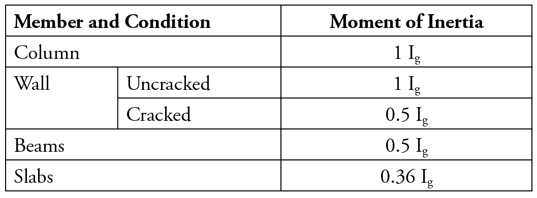
Table of moment inertia permitted for elastic analysis at service load level.
The factors shown in the Table are calculated by multiplying the moment of inertia factor for strength load level stipulated in Table 6.6.3.1.1 by 1.4 as stated in R.6.6.3.2.2 of ACI 318-14.
Seismic and Wind Drift
Both seismic and wind drift are lateral deflections that take place because of applied lateral design forces, but they have many differences, such as allowable drift limits, nature of drift, and determination procedures. The main differences are summarized as follows:
- Seismic drift is recognized as inelastic drift because of the inelastic behavior of the seismic force-resisting system. Thus, a deflection amplification factor, Cd, is used to account for an inelastic drift. On the other hand, wind drift is considered an elastic drift because the wind force resisting system interacts linearly with the design wind forces. Nonlinear response of the wind force resisting system is not permitted. This can be clearly seen from the strict allowable drift limits under wind loads as compared with the relaxed allowable seismic drift.
- Seismic drift of structures is determined at the strength-load level (Strength Limit). However, wind drift is still regarded as serviceability limit and is obtained at service load level (service wind speed with return period of 10, 25, 50, 100 years).
- ASCE 7-16 and ACI 318-14 have explicitly stated that the effect of reinforced concrete cracking shall be considered for obtaining realistic estimates of seismic drift. Yet, they do not state the same for wind drift. ACI 318-14, instead, states in its Commentary that, for wind design, effective stiffnesses representative of pre-yield behavior may be appropriate because the philosophy of wind design does not allow the nonlinear response.
- Allowable drift limits for structures under wind and seismic forces are, to a great extent, different because of the different design philosophies. The allowable drift limits of seismic force-resisting systems are much higher than those permitted for wind force resisting systems. The allowable drift limit for certain seismic systems is about 10 times the drift allowed under wind loading.
Conclusion
One of the inherent provisions in most codes and standards is the consideration of building drift under seismic and wind loading. This must be thoroughly addressed because of the high importance of drift control on structural systems and nonstructural elements, such as partitions, glass, and other brittle components. There are many reasons that necessitate limiting drift; the most significant is to address the structural importance of member inelastic strain in the case of seismic design and system stability and to limit damage to non-structural components, which can be a threat to safety, health, and welfare of the public.■
References
ASCE/SEI 7-16, Minimum Design Loads and Associated Criteria for Buildings and Other Structures. Reston, Virginia: American Society of Civil Engineers, [2017]. Chapter 12.
Seismic design of reinforced concrete special moment frames: A guide for practicing engineers, Second Edition, GCR 16-917-40, NEHRP Seismic Design Technical Brief No. 1, produced by the Applied Technology Council and the Consortium of Universities for Research in Earthquake Engineering for the National Institute of Standards and Technology, Gaithersburg, MD. NIST (2016). 7-11.
NEHRP Recommended Seismic Provisions for New Buildings and Other Structures volume I: Part 1 Provisions, Part 2 Commentary FEMA P-1050-1/2015 Edition. Chapter 12.
ACI (American Concrete Institute). 2014. Building Code Requirements for Structural Concrete and Commentary. ACI 318-14, Farmington Hills, Michigan. Chapter 6 and chapter 18.
Modeling Assumptions for Lateral Analysis, J.F. Horvilleur, V.B. Patel, and K.A. Young. Volume – 240, Farmington Hills, MI. 73-100.