
Curtain walls use extruded aluminum mullions to support glass lites, which are subjected to wind pressures acting inward and outward on the building exterior (Figure 1). The primary loading on mullions is flexure, but determining their flexural strength is complicated by several factors:
- Mullions are usually unsymmetric about their bending axis.
- Mullions are often composed of an assembly that employs a snap-in piece.
- Mullions often use a thermal break, resulting in a composite beam.
- Glass attached to the mullions partially restrains them against twisting or lateral movement.
- Transverse loads are usually not applied at the mullion’s shear center.
- Either extreme fiber of the mullions may be in compression.
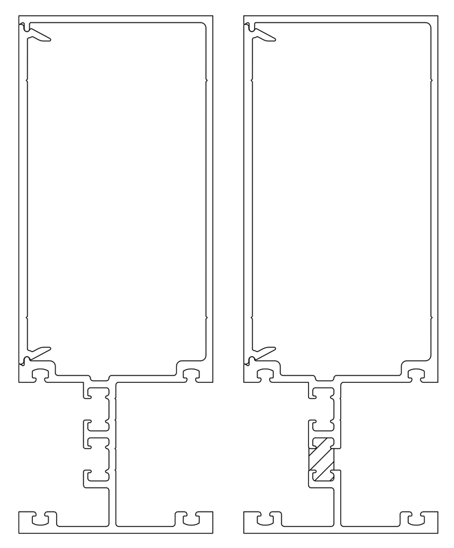
Figure 1. Extruded aluminum mullion assembly without and with thermal break.
Consequently, approximate methods have been devised to predict flexural strengths, but approaches vary widely, and testing is often required. The 2015 and 2018 editions of the International Building Code (IBC) require that aluminum construction complies with the 2015 edition of the Aluminum Association’s Aluminum Design Manual, Part I – Specification for Aluminum Structures, which addresses flexural strength of aluminum extrusions; however, many designers have difficulty applying the Specification’s provisions to mullions. This article discusses the Specification’s provisions for mullions’ flexural strength. References below are to the Specification.
Mullions are usually 6xxx series aluminum alloy extrusions, often 6063 in T5 or T6 temper. For 6063-T6, the Specification gives the minimum tensile yield strength Fty as 25 ksi, minimum tensile ultimate strength Ftu as 30 ksi, and modulus of elasticity E as 10,100 ksi. Thus, the mullion material has slightly less strength and considerably less stiffness than mild carbon steel.
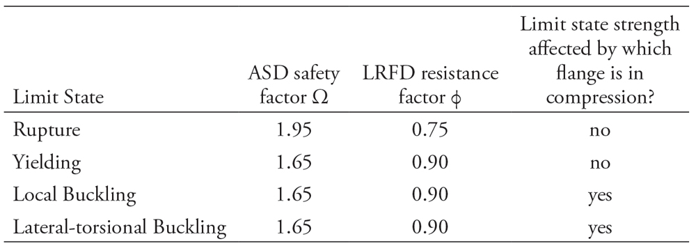
Table 1. Flexural strength limit states.
Chapter F identifies four flexural strength limit states listed in Table 1. Allowable Strength Design (ASD) or Load and Resistance Factor Design (LRFD) methods may be used to determine the available strength; the nominal strength is the same for both. The available flexural strength is the least of the available strengths of the limit states.
As Table 1 shows, Section F.4.1 prescribes safety factors Ω of 1.95 for rupture and 1.65 for all other flexural limit states, and resistance factors φ of 0.75 for rupture and 0.90 for all other flexural limit states. Nominal strengths are divided by the safety factor or multiplied by the resistance factor to determine the available strength.
Rupture and Yielding
Section F.2 addresses rupture and yielding. The yielding and rupture limit state strengths (the plastic moment Mnp = ZFty and the ultimate moment Mnu = ZFtu/kt, respectively) are straightforward to determine once the plastic modulus Z is calculated (kt is a factor greater than or equal to 1 that accounts for notch sensitivity of certain aluminum alloys).
For ASD with 6063-T6, Fty/1.65 = 15.2 ksi and Ftu/1.95 = 15.4 ksi, so ASD available strength is governed by the yield limit state. For LRFD, 0.9Fty = 22.5 ksi and 0.75Ftu = 22.5 ksi, so available strengths for rupture and yielding are equal. Because the lateral-torsional buckling strength is limited to the plastic moment, the plastic moment affects the lateral-torsional buckling strength.
Local Buckling
Section F.3 addresses local buckling (buckling of elements of the cross-section). Figure 2 shows local buckling of a square tube bent about a diagonal axis with the upper sides in compression.
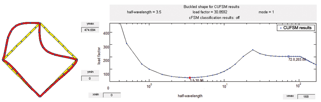
Figure 2. Local buckling of a square tube.
Specification Section B.5.4 provides local buckling strengths for elements in uniform compression and Section B.5.5 for elements in flexural compression. Strictly speaking, no element in a beam is in uniform compression, but elements that are thin relative to their distance from the neutral axis, such as the flange of I shapes, can be idealized as such. The Specification addresses four cases of uniform compression and two cases of flexural compression for flat elements of constant thickness like those encountered in mullions. Ignoring small grooves or projections common in mullions usually does not significantly affect accuracy.
In reality, each element’s local buckling strength depends on the support given to that element by other elements of the shape; separately determining each element’s strength does not account for this. This interaction is approximated, however, by averaging the elements’ strengths using Section F.3.1. This approach requires dividing the shape into flange elements (elements in uniform compression) and web elements (elements in flexural compression) and determining the moment of inertia of each group.
Section F.3.2 provides another way to determine the shape’s local buckling strength: the Direct Strength Method (DSM), also used in the AISI cold-formed steel specification. This method uses software such as CUFSM (Constrained and Unconstrained Finite Strip Method) to determine the elastic local buckling strength of the entire shape. This elastic buckling strength is then used to determine the actual compressive strength, whether it be yielding, inelastic buckling, or elastic buckling. CUFSM determines the elastic buckling strength of any assembly of rectangular elements, accounting for interactions between elements. Designers can include any of the extrusions’ grooves or projections that they wish.
CUFSM also determines section properties for any open shape, including the warping constant Cw, location of the shear center, and coefficient of monosymmetry β, which are often difficult to determine but needed to calculate the lateral-torsional buckling strength. CUFSM determines the coefficient of monosymmetry about the two principal axes – not the geometric axes – but these are usually nearly the same for mullions. CUFSM does not account for which side of the neutral axis is in compression, so the user must determine the sign. For unsymmetric I beams, for example, β is positive when the larger flange is in compression and negative when the larger flange is in tension.
Lateral-Torsional Buckling (LTB)
Because the tension side of the neutral axis is pulled straight while the compression side of the neutral axis buckles laterally, lateral-torsional buckling twists the cross-section (Figure 3).
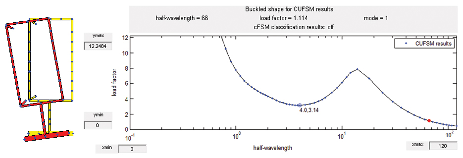
Figure 3. Lateral-torsional buckling.
As many mullions are unsymmetric about the bending axis, the only Specification Section that applies to all mullions is F.4.2.5, which determines the slenderness from the elastic LTB moment for such shapes. Section F.4 can then be used to determine the actual LTB moment, which may be elastic or inelastic, from the slenderness.
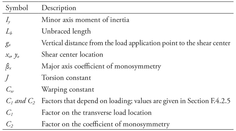
Table 2. Section properties required by equation F.4-9 to determine LTB strength.
Either equation F.4-9 (below) or the Direct Strength Method can be used to determine the elastic LTB moment. While equation F.4-9 requires the section properties listed in Table 2, these can be determined for any open shape using CUFSM or other software. Equation F.4-9 addresses beams with the transverse load applied at any location; CUFSM always applies the transverse load at the shear center.
Complicating Factors
Thermal breaks (thermal barriers) are often provided in aluminum mullions. One type, called “poured and debridged,” is created by pouring an elastomer into a cavity in the extrusion and then removing the aluminum bridge at the bottom of the cavity. If the barrier’s modulus of elasticity is known and it remains intact until the mullion reaches another limit state, calculating the composite beam’s flexural strength is straightforward.
Equation F.4-9 can approximate the barrier’s effect by factoring its width by its modular ratio, n, the elastomer’s modulus of elasticity divided by aluminum’s modulus (10,100 ksi). For a commonly used elastomer with a modulus of about 250 ksi, n = 250/10,100 = 0.025. Alternatively, CUFSM can be used to analyze shapes with multiple materials. The American Architectural Manufacturers Association’s (AAMA) technical information report, TIR-A8, further addresses structural aspects of thermal breaks.
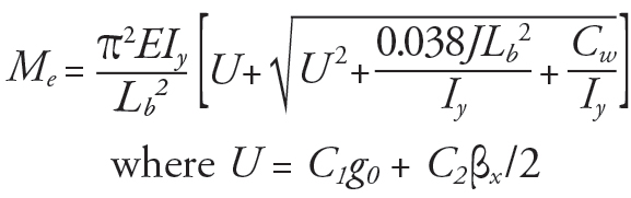
Aluminum extrusions can be snap-fit together without fasteners or adhesives by elastically flexing the parts past a catch point, so they lock. The coefficient of friction between aluminum parts varies significantly depending on surface conditions, and part clearances vary due to tolerances. Consequently, snap-fit joints provide little resistance to rotation at the joint. The snap-in part, however, effectively restrains relative movement of the parts in the two orthogonal directions in the shape’s cross-section. It thus significantly contributes to the mullion’s torsional stiffness and LTB strength, as well as affecting the local buckling strength. CUFSM can model the assembly with these restraints as shown in Figure 4.
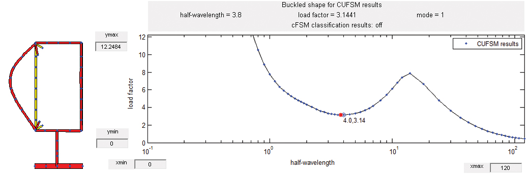
Figure 4. Local buckling of a snap-in assembly.
The same wind load acts on the glass on each side of a typical mullion; this symmetrical loading restrains the mullion from twisting about its longitudinal axis at the glass pocket. This restraint can be modeled by DSM and may be on the compression side of the neutral axis or the tension side of the neutral axis, with differing effect on flexural strength. In one example, the LTB strength with rotational restraint was 3.5 times the strength without restraint. The glass is not assumed to restrain the mullion against translation in any direction.
Table 3. DSM pros and cons.
Table 3 lists the pros and cons of using DSM for determining flexural strength. While neither addresses all issues, DSM addresses all but the location of the load with respect to the shear center. If the transverse load acts towards the shear center, the LTB strength is less than if the transverse load acts at the shear center; neglecting this effect overestimates the LTB strength. Conversely, if the transverse load acts away from the shear center, the LTB strength is greater than if the transverse load acts at the shear center. Equation F.4-9 can be used to determine the sensitivity of the LTB strength to the location of the transverse load. Thus, DSM provides a powerful tool to address the complicating factors affecting the flexural strength of aluminum mullions.■