
Situated along the historic San Francisco waterfront on San Francisco Port Authority property, a dilapidated former shipbuilding complex from the late 19th and early 20th century has been revitalized as part of a massive adaptive reuse project (Figure 1). The Pier 70 complex was the location of Union Iron Works, a premier West Coast shipbuilding facility through World Wars I and II until it was shuttered several decades ago. The anchor of the complex is Building 113/114, a two-block-long brick and steel building.
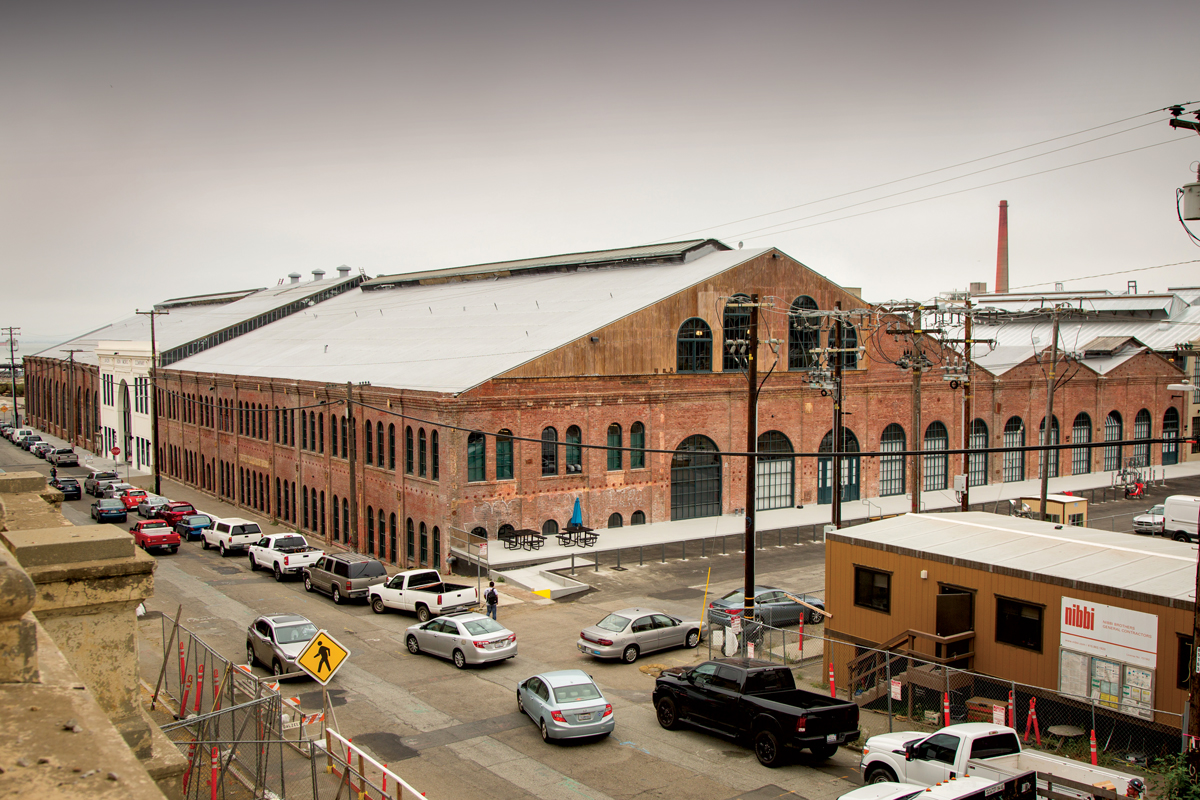
Figure 1. View of Building 113/114 from the Northwest.
It was initially constructed as two buildings in 1885 and 1886, and subsequently joined by a reinforced concrete and steel “connector building” in 1914 (Figure 2). The nearly 500-foot-long, over 60-foot-tall, 82,000-square-foot building was built to serve as Union Iron Works’ machine, blacksmith, and boiler shops. Orton Development, Inc., Marcy Wong Donn Logan Architects, Mark Hulbert Preservation Architecture, Nibbi Brothers General Contractors, and Nabih Youssef Structural Engineers teamed up to bring the historic building back to life.
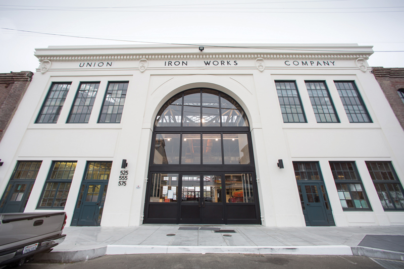
Figure 2. View of connector building.
Building History
The building was primarily constructed of tall unreinforced masonry (URM) perimeter walls with steel trusses spanning between the perimeter walls and interior cast iron columns. The long-span steel trusses used for the gable roof create a dramatic interior volume (Figure 3).
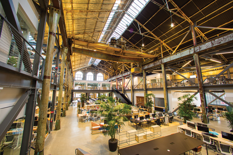
Figure 3. Interior view of Eastern wing of Building 113.
Heavy-industrial structural steel crane rails and associated support steel is located throughout the facility, offering a glimpse back to the former shipbuilding days. Through over a century of service as an active ship-building facility, innumerable small and large alterations resulted in limited structural conditions that could be considered “typical.” As a result, an extensive field investigation was necessary before design and construction commenced. Heavy involvement by the structural engineers was also required during the construction phase to deal with the numerous atypical conditions that were uncovered.
Despite construction methods that are considered brittle and fragile by today’s standards, and an incomplete lateral-load-resisting system, historical records indicate that the building performed relatively well in the 1906 Great San Francisco Earthquake and the 1989 Loma Prieta earthquake. In fact, part of the modern retrofit work included reviewing historical reports, photos, and engineering drawings for relatively minor repairs performed after the 1906 event. Damage from the 1906 earthquake was limited primarily to the out-of-plane failure of two sections of brick walls on the east and west sides of the building. Fortunately, these two sections of wall were not significant load-bearing elements, so the stability of the structure was maintained. The two sections of wall were subsequently replaced with corrugated metal cladding, and the ship-building activities resumed. It is believed that the large steel and cast iron gravity frame that was intended to support the crane in the building acted as a secondary lateral-resisting system to brace the top of the URM perimeter walls.
Building 113/114 is the focal point of the Pier 70-20th Street historic corridor, which includes many of the most historically significant buildings along San Francisco’s waterfront and is the easternmost segment of the rapidly developing Dogpatch neighborhood. At the end of its prior life, Building 113/114 was abandoned and red-tagged due to the damaged and noticeably leaning perimeter URM walls. Years of service in a marine environment, low-quality historic mortar, and poor soil conditions combined to take a toll on the perimeter walls, causing them to crack and visibly lean upwards of 18 inches out of plumb. A seismic retrofit – which was mandated by the Port of San Francisco building code because of the URM construction – and the adaptive reuse brings an abandoned treasure back into service.
Seismic Retrofit Scheme
Collaboratively, the developer, general contractor, architects, and structural engineer aimed to develop a seismic retrofit that would stabilize the perimeter URM walls, provide enhanced seismic performance, and provide additional square footage (where possible). The resulting scheme utilizes two new levels of perimeter framing to stabilize and brace the perimeter walls (Figure 4). The first level of new framing braces the walls at mid-height and creates a lower mezzanine that significantly adds to the square footage of the building. The second level of new framing is an unoccupied upper mezzanine composed of horizontal steel diaphragm trusses used to brace the top of the walls and supplement the deficient existing roof diaphragm. This approach also allowed the existing roof diaphragm to remain largely as-is, thus preserving the historic character and avoiding substantial strengthening to brace the walls out of plane. A horizontal steel truss was selected to recreate the look of an existing heavy timber horizontal truss that was utilized at the same location to brace the original crane rails (Figure 5).
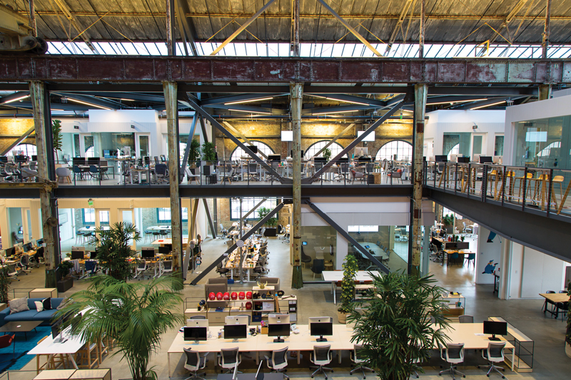
Figure 4. View of buckling restrained braced frames.
By locating the mezzanines around the perimeter, the spacious interior volume was preserved along the building’s central spine. Both new mezzanines were utilized as diaphragms to laterally support the massive unreinforced masonry walls out of plane. Thru-bolts were used to tie the diaphragms to the walls and incorporated vintage plate washers to better align with other thru-bolts that had been added over the life of the building. The mezzanine slab edge is pulled back from windows to minimize the visibility from the exterior.
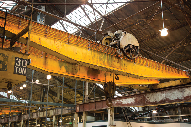
Figure 5. View of historic crane.
A complex new steel frame was added within the existing building to provide a gravity system to support the new mezzanines and a lateral system for both the new mezzanines and the remainder of the existing building. Strengthening and reusing the existing columns was studied but, because they are constructed of brittle cast iron, this approach was ultimately abandoned in lieu of an approach that provides new columns strategically located to minimize their visibility.
Buckling-restrained braced (BRB) frames provide lateral resistance for the new and existing elements. This system was chosen over a moment frame to limit seismic drifts and over a special concentrically braced frame (SCBF) system because of improved seismic performance. The new gravity-and-lateral-framing system essentially creates a “building-within-a-building” and uses the roof and perimeter URM walls as cladding-only, thus completely relieving the seismic demands of the existing structure. The existing, leaning URM walls were ultimately not straightened, so the lateral braces and diaphragms were designed to resist the horizontal forces due to the permanent lean in the walls.
Since an entirely new lateral-load-resisting system was created, the seismic system was designed based on the requirements of the 2013 California Building Code (CBC) for new buildings. A linear dynamic analysis was performed using SAP 2000 software to design the seismic system. The geotechnical engineer, Langan Engineers, developed a site-specific response spectrum. A global, capacity-based design approach was incorporated by designing the diaphragms, connections, beams, columns, and foundations based on the capacity of the braces. This allows the braces to act as the fuse in the seismic-force-resisting system while protecting other elements of the system.
Integrating the new structural system into the existing structural system was a key design goal and one of the most significant challenges of the project. The historic fabric of the structure had to be maintained while balancing structural safety. Extensive coordination between the design architect, historic architect, general contractor, and structural engineer was required to locate nearly every new structural element within the existing building. Because no two parts of the building are symmetric, field verification for nearly every new above-grade element and exploratory excavation for every below-ground element was required.
Foundations and Bridges
The foundation design was particularly challenging, as the building straddles the historic shoreline such that one half of the building is founded on rock and the other half is underlain by up to approximately 20 feet of fill that is susceptible to liquefaction. The fill was obtained by partial demolition of the adjacent Irish Hill, so named for the large population of Irish shipbuilding workers that inhabited the hill in the 1800s and early 1900s. A foundation system that included a combination of shallow footings over bedrock and a system of micro-piles joined by grade beams allowed new columns to be placed in the architecturally desirable locations, typically adjacent to existing columns. The new foundations are adjacent to, or even spanning over, existing foundations. Deep foundations were typically required at braced-frame locations because the frames resisted the lateral load of the heavy perimeter walls but supported minimal dead load of the mezzanines. Micro-piles, which are small diameter drilled and grouted piles, were selected because of their large uplift capacity, a minimal amount of spoils (the site soil is believed to be contaminated), and because the drill rig could be driven into difficult areas to access locations within the existing building.
New long-span steel bridges were incorporated to offer a striking addition to the central spine, provide for circulation within the mezzanines, and add square footage to the building. The bridges, designed with tapered end-plate girders to mimic the existing crane girders of the machine shop that remain as historic elements, also serve a key role in seismically linking the disparate mezzanines throughout the building. This allows the building to behave more uniformly in a seismic event.
Interior Spaces
In addition to the global Building 113/114 retrofit, there were multiple small-scale retrofits of the existing wood framed ‘buildings’ contained within the overall building. These spaces had been constructed at various times and served as offices and storehouses. They were constructed with materials that varied even more than the overall building. Each small building retrofit required multiple structural interventions, including new shear walls, strong-backs, and connections to the primary steel structure. Saving these spaces from wholesale demolition and turning them into unique modern office spaces that greet visitors at the main entrance contribute to the character and historic feel of the overall building.
Upgrade of Perimeter Walls
Although the existing perimeter walls are now considered as cladding to the new steel frame, their severe deterioration still required a substantial amount of refurbishment. An extensive survey of the existing thick perimeter URM walls, typically constructed of three wythes of brick, was conducted to determine their current state and to develop a methodology to upgrade them. Despite their deteriorated condition and visible lean, preserving their historic character and finish was critical to the success and personality of the project. Various tactics were used on a case-by-case basis including repointing mortar joints inside and out, installing ties to join wythes together, retrofitting foundations, and, most importantly, installing anchor bolts to tie the walls to the new concrete and steel framed mezzanines. Some areas had deteriorated to such a degree that wholesale rebuilding with salvaged historic bricks was required. The ability of the walls to arch out of plane under seismic loading was evaluated based on h/t (height/thickness) and compared to limits contained in the URM retrofit building code. Where limits were exceeded, HSS strongback members were added to span between floors and brace the walls.
Conclusion
The adaptive reuse of this project brings new life to an otherwise abandoned building. The new structural system was integrated into the existing building in a way that preserved the historic character, with the goal of allowing another century of use in this blossoming neighborhood on the San Francisco waterfront. Building 113/114 is currently complete and houses two technology tenants. The connector building is open to the public and links 20th Street to an internal public piazza, which was repurposed and intended to be used for community events.
The Design Team has also collaborated to seismically retrofit Buildings 14, 101, 102, 104, 115 and 116 within the same Pier 70 complex, creating approximately 300,000 square feet of mixed-use development. A second phase of the development, spearheaded by developer Forest City, will involve retrofitting several other buildings while constructing several million square feet of new construction to complete the nearly 70-acre Pier 70 site. Building 113/114 is a significant component of the revitalized district, and its completion serves as a major milestone for the overall development.■
Photos courtesy of Dave Zahrobsky.