
Earthquake engineering professionals generally recognize that unreinforced masonry buildings of most vintages pose a significant risk of collapse in strong earthquakes. Cognizant of this, the City of San Francisco enacted an ordinance that required assessment, and either upgrade or demolition, of any such building within the jurisdiction found to be deficient regardless of its historic, cultural, or aesthetic significance. Sherith Israel was one such building. The story of how it was literally saved from the wrecking ball by diligently treating seismic safety and historic preservation objectives with equal priority, and by employing a host of new technologies in concert with traditional ones to surmount technical challenges, is described herein.
Temple Sherith Israel
Constructed in 1904, Temple Sherith Israel was designed by Albert Pissis, a prominent San Francisco engineer/architect trained at Ecole des Beaux-Arts, and is on the National Register of Historic Places (Figure 1). The ornately painted interior of its vast sanctuary is one of the last surviving mural interiors by turn-of-the-century artist Attilio Moretti. The sanctuary space is framed by large opalescent stained-glass windows designed by Albert Pissis’s brother, Emile (Figure 2). The building also houses one of the last surviving Murray Harris organs. The vast sanctuary and the room in which the machinery and pipes for the organ are housed together occupy more than 90 percent of the plan area of the building, which created a significant challenge for establishing seismic improvements.
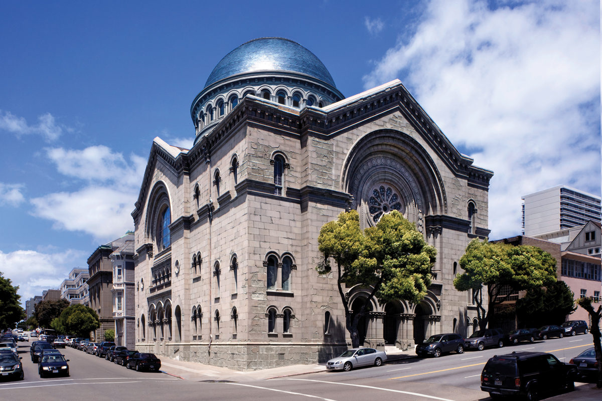
Figure 1. Sherith Israel exterior. Courtesy of David Wakely.
The building shell consists of thick, multi-wythe brick masonry bearing walls that rise to roughly 75 feet at the gables and are clad with Colusa sandstone. The east, west, and south walls are articulated in plan and incorporate large corbelled arch substructures that span over large openings and provide out-of-plane stability. The north wall is nearly planar, without significant openings or ornamentation. The sanctuary is capped by a steel-framed, zinc-clad, 60-foot-diameter drum and a dome that rises to roughly 100 feet above the sanctuary floor and naturally lights the sanctuary interior.
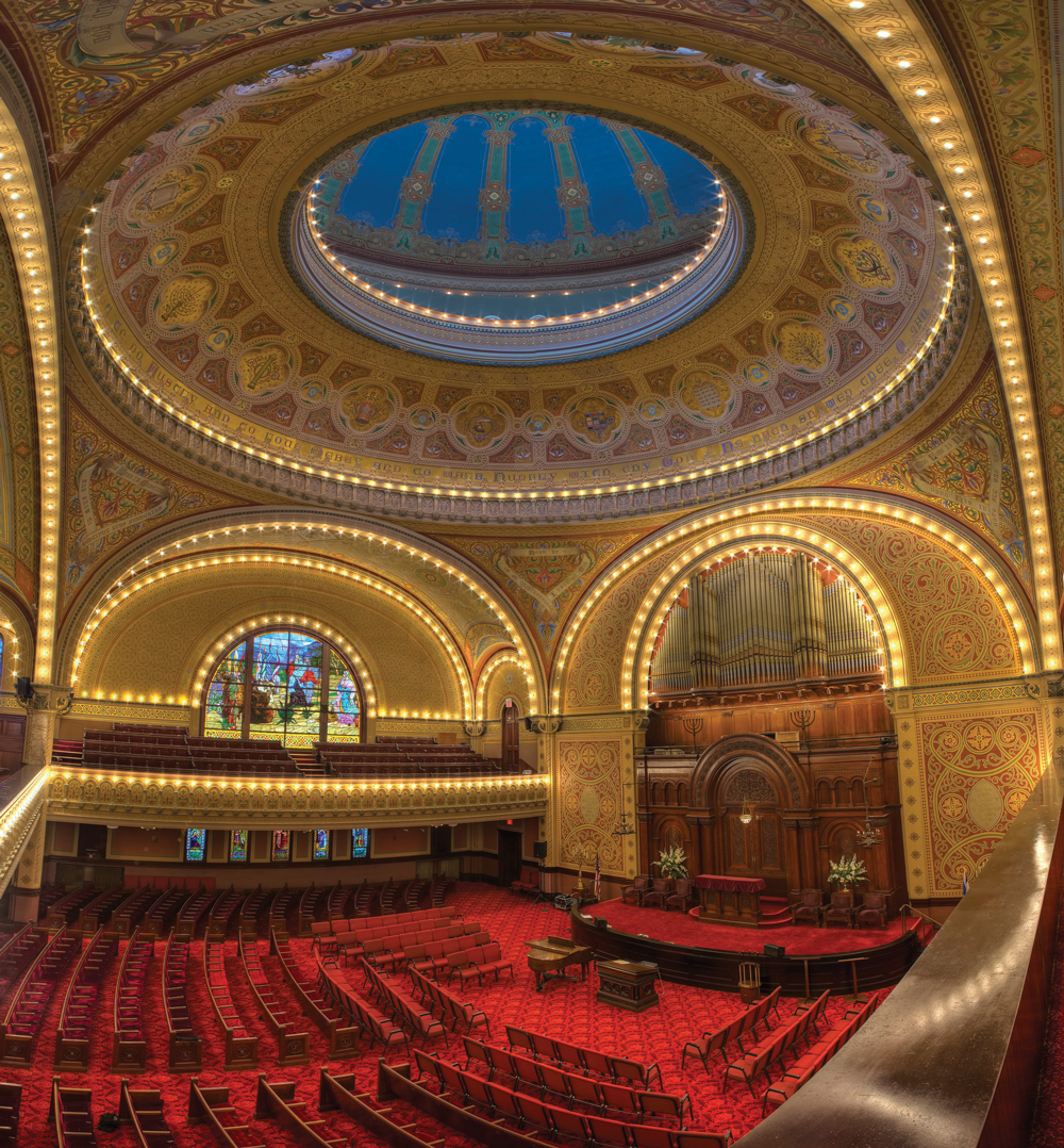
Figure 2. The sanctuary of Sherith Israel. Courtesy of Bruce Schneider.
Surviving the “Great 1906 Earthquake” with only modest damage to cornices, gable end wall masonry, and interior plaster, Sherith Israel temporarily served as the Hall of Justice following the collapse of San Francisco City Hall in that event. Archival records indicate that the south gable end wall detached from the roof framing, sufficient to require rebuilding of the masonry in that area. Also, existing conditions indicated that out-of-plane movement of two other gable end walls resulted in permanent relative displacement between the steel “outrigger” beams and the end walls, resulting in local cracking and partially dislodged brick where the beams were partially withdrawn from their bearing. Thus, the ground shaking during 1906 was apparently strong enough to initiate, but not complete, a failure sequence commonly observed in masonry buildings with gable end walls. Nonetheless, the comparison between its behavior and that of other large URM buildings in the neighborhood at the time suggests that Sherith Israel is a more competent building than many of its unreinforced brethren.
Design Philosophy
Subject to San Francisco’s ordinance, and having an assembly usage, Sherith Israel was required to meet more stringent seismic upgrade requirements than ordinary structures. The congregation solicited engineering concepts to satisfy the ordinance; however, the concepts relied on brute force interventions that supplanted rather than supplemented the inherent strengths of the existing structure and did not defer at all to the historic character of the building. The proposed massive concrete shear walls, heavy structural steel bracing, and replacement of existing wood diaphragms with concrete and metal deck systems would have largely destroyed the very historic characteristics of the property that the congregation cherished.
Employing these strengthening techniques in this structure was counterproductive in another important respect: they would have destroyed the beneficial dynamic separation between in-plane and out-of-plane modes of the masonry walls that was key to the structure’s superior performance during the 1906 earthquake. That separation resulted from the very flexible diaphragms and open sanctuary interior that allowed the seismic mass associated with out-of-plane wall behavior to respond at spectral accelerations well off the spectral plateau. Elimination of that separation would have required more lateral resistance than the extant masonry walls could provide without supplementation. Although these commonly employed strengthening concepts all could have been engineered to satisfy the ordinance, by discounting the inherent strengths of the existing structure, radically altering its original dynamic characteristics, and needlessly disrupting historic integrity, the concepts were all rendered infeasible with respect to preservation, cost, and the desires of the congregants.
In contrast, preservation of this behavior would eliminate the need for supplementation of story shear strength and was made a design priority, second only to the goals of preserving the historic fabric of the building and complying with the City’s seismic requirements. In California, the California Historical Building Code (CHBC) is permitted to be used for qualified historic properties. In recognition of the special conditions encountered in dealing with archaic materials and construction, the CHBC contains fewer prescriptive requirements and provides broad discretion for the use of alternate materials and methods of construction. Based on the provisions in the CHBC, the prior performance during the 1906 earthquake was used to benchmark the strengths and weaknesses of the structure. A number of alternate strengthening methods were identified which, as part of the overarching “do no harm” project philosophy, could be installed with little or no disruption to the structure’s character-defining features. In the end, the sanctuary was left undisturbed, despite it occupying the vast majority of the building plan. Everything visible in Figure 2 is original; other than some localized repairs to correct prior water damage, this post-retrofit photo is indistinguishable from the pre-retrofit condition of the sanctuary.
Seismic Strengthening Techniques
Avoiding disruption to the extraordinary historic character of Sherith Israel required a creative approach that utilized state-of-the-art measures, in concert with more traditional interventions like a roof level bond beam and floor-to-wall ties that could be surgically installed.
Center Cores
To improve the overall integrity of the bearing walls, center-cored reinforcement – which the designers viewed as “integrity steel” – was added to the unreinforced masonry. The center core technique generally involves coring a hole within the unreinforced masonry, installing a steel reinforcing bar in the hole, and filling the hole with grout – in effect reinforcing the unreinforced masonry. The reinforcement was not numerically relied on to provide supplemental masonry shear strength. The primary goal of the center cores was to preclude uncontrolled cracking and separation of the masonry, thereby reducing the likelihood of large blocks of masonry dislodging and increasing the toughness of the bearing wall system. Due to the sensitivity of the historic finishes, the coring was accomplished without water, primarily from the roof, which required threading cores as long as 75 feet down through the masonry and also anchoring the reinforcement into a new perimeter bond beam at the roof.
In the case of Sherith Israel, roughly 20 percent of the more than 6,000 linear feet of cores that were installed were horizontally-oriented. These cores were used to stitch masonry corners together and to control “unfolding” of the walls at plan articulations. A polymer grout was engineered specifically for the project to match the stiffness of the masonry, reduce shrinkage, reduce thermal cracking, reduce cost, and prevent damage to water-sensitive interior plaster finishes. The polymer binder in the grout also impregnates the adjacent porous masonry materials as it bleeds, improving integrity in the process.
Octagonal Tension Ring
Gable end walls are known to be susceptible to out-of-plane failures in relatively modest ground motions and, in the 1906 event, out-of-plane gable end wall failure at the south wall was underway. To reduce the vulnerability of the gable end walls, an octagonally-configured tension tie system with super-elastic nitinol “fuses” was added in the attic to promote re-centering and control out-of-phase, out-of-plane behavior of the gable end walls and the main arches that support them.
Nitinol is a super-elastic, temperature-dependent, shape memory/ nickel-titanium alloy. Its use on this project is believed to be the first use of nitinol for seismic resistance in North America. Nitinol’s primary use is in medical devices for which it can be engineered to provide precisely specified properties, depending on the device. The project’s structural engineers selected an off-the-shelf product that provided the desired properties within the normal temperature range of the attic – fully recoverable strain to roughly five percent to assist in re-centering and a “yield stress” of approximately 80 ksi at a strain of 1 percent – and identified a technology for installing it within the balance of the tension tie system. Prototypes of the nitinol subassembly were subjected to testing in laboratories to confirm that these “fuses” would perform as intended. Figure 3 shows the stress-strain curve of the nitinol.
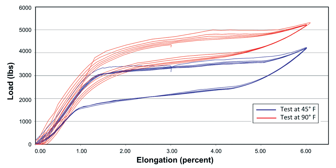
Figure 3. Stress-strain curves developed from testing of nitinol subassemblies.
In many ancient houses of worship around the world, tension ties traverse the sanctuary interior. However, in this case, passage of the tension ties through the murals on the interior dome and across the sanctuary interior was judged to be too disruptive. To circumvent the sanctuary interior completely, a “tension ring” concept was implemented using steel Dywidag rods that run parallel to and hang from each of the eight original riveted plan-octagonal structural steel trusses that support the main drum and dome. The structural steel nodes of the octagonal tension ring are the reaction points for loading by the nitinol fuse assemblies, which are comprised of small-diameter nitinol wires in a loom-like support structure (Figure 4) that was designed to be lightweight, easy to fabricate and install, and easy to anchor to the masonry.
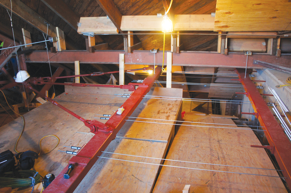
Figure 4. View of nitinol fuses as installed in the attic of Sherith Israel
Compression-Only Concrete Pilasters
The north elevation of Sherith Israel, hardly visible from the street and facing a narrow walkway that is required for emergency exiting, is a mostly solid, mostly planar, four-wythe thick masonry wall. Without significant folds, this wall is far more prone to out-of-plane instability than the other perimeter walls, as evidenced by the inclined cracks that were caused by the 1906 earthquake and remain visible in several adjacent perpendicular plaster walls. Four reinforced concrete pilasters with unusual capabilities and geometries were designed for the north wall (Figure 5) to supplement its stability.
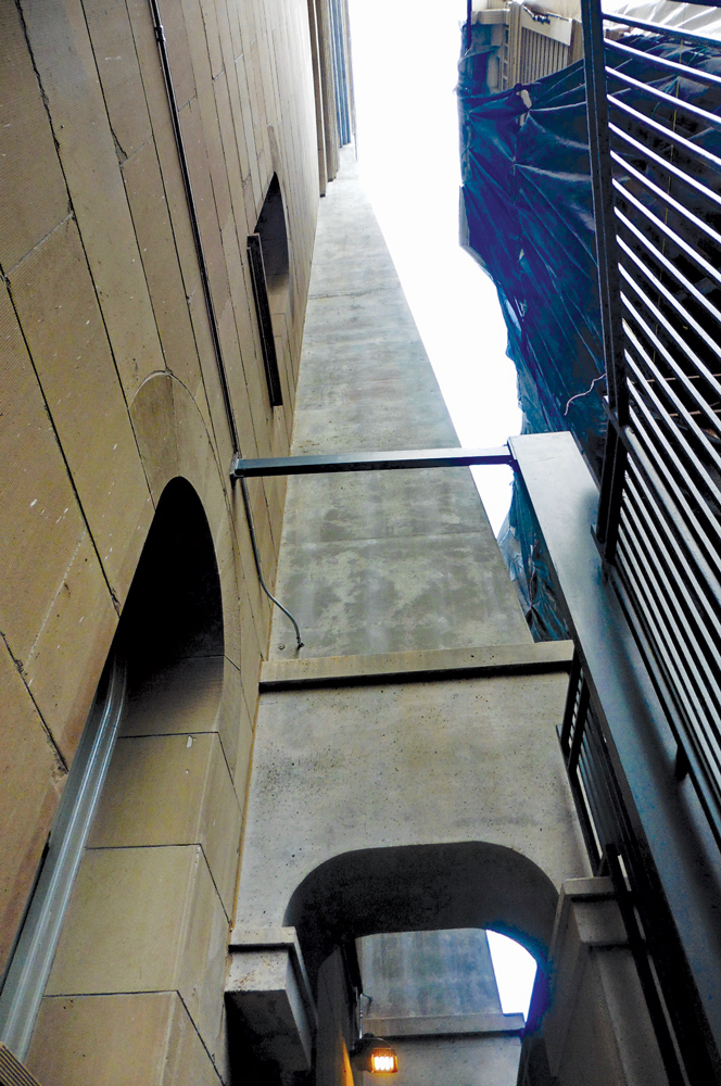
Figure 5. Pilaster end supported on rocking block in north alley. Courtesy of Charley Stern.
The pilasters were necessary to preclude the north wall falling outward from the building toward the north, but a typical pilaster designed to preclude northward instability would also stiffen the wall against southward displacement. Restraint against southward displacement was judged to be undesirable because, when the building displaces toward the south during an earthquake, the stiffened north wall could be torn free from the structure. To provide the necessary support against northward instability while permitting southward movement, the pilasters, dimensioned to approximate the plan articulations in the other three exterior walls, were designed to uplift when the building moves to the south and the base of each pilaster was designed to freely translate by supporting it on a “rocking block”.
Fiber-Reinforced Polymer Catenary
To address a portion of the north wall masonry with an excessive span-to-thickness ratio between the above-described rocking pilasters that was not accessible for center-coring, a horizontal strip of sandstone veneer was temporarily removed to install a “catenary” of fiber-reinforced polymer (FRP). This FRP catenary was anchored to the nearby compression-only pilasters and concealed within the veneer’s mortar bed, thus reinforcing the masonry out-of-plane and allowing it to span horizontally between pilasters.
Backup Support for Plaster Ceiling Framing
To reduce the likelihood of collapse of the heavy plaster vaulted and domed ceilings over the sanctuary, backup support for the ceilings was achieved by conversion of gable roof rafters into trusses. This was accomplished via the addition of threaded rod tension members in the attic, across the gables, and by addition of secondary suspension wires that connect the ceiling framing to the newly formed roof trusses. Relative to the incremental safety they provided, these additions were incredibly cost-effective with respect to both materials and labor required to convert the gables to trusses and to add the hanger wires.
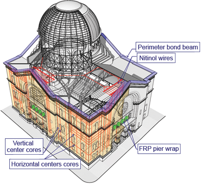
Figure 6. Schematic cut-away diagram showing some of the strengthening measures that were implemented. Courtesy of ELS Architecture and Urban Design.
Figure 6 shows a schematic cut-away diagram highlighting some of the strengthening measures that were taken during the project.
Conclusions
More than one hundred years after the Temple Sherith Israel resisted the 1906 earthquake with relatively minor structural damage, the building has undergone an extensive historic renovation and seismic strengthening, meeting San Francisco’s upgrade requirements for unreinforced masonry buildings and precluding the need to abandon and demolish the structure. Key, from a structural standpoint, were the efforts taken to understand the inherent positive seismic characteristics of the building and the framework of the California Historical Building Code, which permits legal recognition of alternate materials and construction in historic preservation projects. ■
Acknowledgments
The authors would like to acknowledge and thank Congregation Sherith Israel, Plant Construction Company, ELS Architecture and Urban Design, and Langan. The WJE team also included Alan Dreyfuss, Daniel Eilbeck, Una Gilmartin, Mahmoud Hachem, Jeffrey Rautenberg, and Owen Rosenboom.