
Terminal 1 Security Checkpoint Building Renovation and Retrofit
The Terminal 1 renovation at Oakland International Airport involved a unique structural solution that helped the airport achieve its goals of continued operations, sustainability, and modernization. The original terminal building dates back to the early 1960s, and consisted of four primary structures, all of reinforced concrete and supported on piles. The terminal was modified over time to follow the changing requirements of air travel, resulting in several additions. The most recent multi-phased renovation and seismic retrofit program started in 2006 with the seismic evaluation of all Terminal 1 buildings. It resulted in multiple construction projects that were delivered using the CM At-Risk method, with a design team led by Bill Olechnowicz of MWA Architects and Turner Construction as the general contractor. Completed projects to date include the seismic retrofit of the concourse and central plant, as well as construction of a new central plant and electrical substation.
The building that is addressed by the seismic retrofit project presented herein functions as a security checkpoint and Port of Oakland offices. It is one of the original four structures and consists of a two-story, above-grade building over a crawl space. The building has plan dimensions of approximately 238 feet by 238 feet. Forty-eight concrete columns, at 34-feet on-center each way, support a normal weight concrete flat slab at the first floor, a lightweight concrete waffle slab at the second floor, and weakly interconnected lightweight precast concrete shells at the roof (Figure 1).
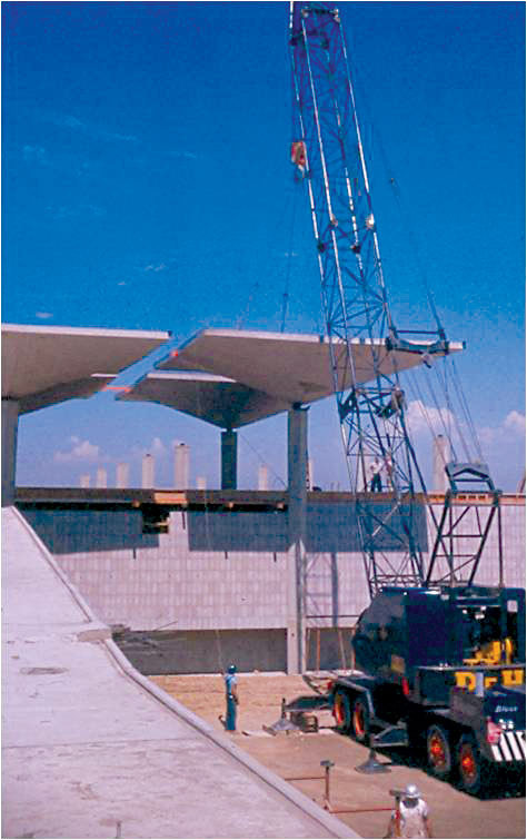
Figure 1. Original construction. Courtesy of Port of Oakland.
The vertical elements of the original seismic force-resisting system consisted of concrete walls at the crawl space level, reinforced masonry walls at the first story, and cantilever columns at the second story. The original Air Traffic Control Tower for the airport was located within the footprint of this building but was seismically separated from the two-story building by a joint. The tower was demolished as part of the renovation and retrofit project, its function having been replaced by a new tower located nearby.
The retrofit scheme for the remaining structure introduced new vertical seismic force-resisting elements at the perimeter, consisting of special reinforced concrete shear walls at the crawlspace and first story, and buckling-restrained braced frames at the second story. Columns and local areas of the existing concrete floor slab were improved using FRP. A new diaphragm was created at the roof level by the addition of a horizontal truss system comprised of hollow structural sections connected at column locations using a cast steel column collar.
Because a new lateral system was provided for the existing structure, design criteria were based on a combination of the 2010 California Building Code and ASCE 41-06, Seismic Rehabilitation of Existing Buildings, with the Basic Safety Objective as defined in ASCE 41-06 as the target performance level. Response spectrum analysis was used, and the base shear from the ASCE 41 analysis was scaled up to 85% of the 2010 CBC static base shear to determine seismic demands on both new and existing elements. Steel roof truss elements are designed to remain elastic while developing the overstrength of the Buckling-Restrained Braces (BRBs), assuming simultaneous yielding of the BRBs in the two orthogonal directions.
Truss Connection Challenges
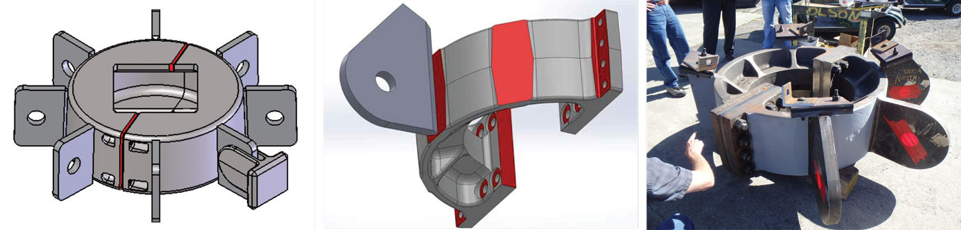
Figure 2. Various design configurations of the cast collar; actual casting on the right.
A key constraint imposed on the project team was that the security checkpoint located in this building needed to remain operational throughout construction to avoid impacts to the traveling public. From a structural perspective, the primary challenge involved the connection of the new truss members at the top of the existing columns. This connection took on many shapes during design to meet the varying demands of strength, constructability, and aesthetics. The original connection of the existing roof shells to the columns resulted in a highly congested, reinforced concrete section at the top of the columns. In addition, roof drainage was routed down each column. To avoid drilling through the column, early concepts for the connection considered a built-up section of steel plates to form a square collar around the column. This approach resulted in a considerable volume of weld material at collar corners. Making these welds in the field would have been very costly and time consuming. As an alternative, a steel casting was explored with Pacific Steel Casting of Berkeley, California. A cross section was developed iteratively in consultation with the architect, contractor, and the foundry that responded to structural requirements, aesthetics, constructability, and production schedules. The collar consisted of two identical halves that are joined around the column in the field, resulting in a total of 96 castings for 48 connection nodes. Welded gusset plates were added to the cast collars for different configurations of brace connections (Figure 2). In collaboration with the contractor, it was decided that welding the cast collar halves together would add complexity in the field, and so the design was further modified to allow field bolting. A C-shaped cross section was revised to a T-shaped one with stiffening ribs at locations where gussets for horizontal truss members could be placed. The T-shape provided better access for bolt installation. This change also facilitated the casting operation since molten metal flows into the pattern (mold) and cools in a more controllable way. Using cast steel became the preferred alternative after mock-ups in the existing structure showed that the shape of the casting could be integrated into the project in an aesthetically pleasing manner. R+C performed a finite-element stress analysis of the casting to determine an acceptable structural configuration. The material chosen for the casting was ASTM 958, Grade SC8620 Class 80/50. This material has properties compatible with ASTM A572 Grade 50, specified for the gusset plates, and ASTM A500, Grade B, specified for the horizontal truss members.
Cast Collar Fabrication Process
Olson Steel was the steel fabricator and erector for the project. They contracted with Cast Connex and Bradken to fabricate the production castings. R+C worked with Cast Connex to further refine the casting design, specifications, and quality assurance/quality control specifications to achieve the appropriate level of quality and reliability of the casting. In addition, Cast Connex/Bradken performed a finite element analysis for the casting production to show how molten metal flows into the casting and cools to optimize the pattern for production. The castings were fabricated in Bradken’s Missouri facilities. Quality control, performed by Bradken, and quality assurance, performed by the Airport’s testing agent Construction Testing Services Inc./Diversified Services, were implemented at Bradken’s production site before the castings were shipped to Olson Steel. A prototypical casting, the First Article, was tested using visual inspection, magnetic particle testing (MT), ultrasonic testing (UT), and radiographic testing (RT). Samples of the casting metal were taken, and tensile tests and Charpy V-notch testing were performed. For the production castings, RT was eliminated and UT frequency was reduced, but the remaining testing was as required for the First Article. Castings were machined to tolerances that would facilitate subsequent steel fabrication; particular attention was paid to bearing surfaces at the bolted collar halves and to surfaces to receive welded gussets.
Cast Collar Erection Process
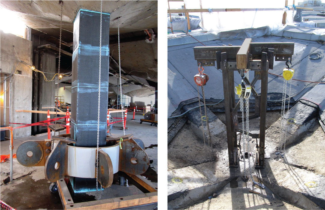
Figure 3. Olson’s lifting rig – to the left is a casting being lifted into place; the rig is on the right. Note the top of the roof ribs.
Olson Steel’s concept for the erection of the cast collars was to place the two halves around columns in the field on the floor level below the roof, bolt them together, and finally lift them into place. Each collar was supported from four existing roof shell ribs using a through-bolted bearing connection. Given that each collar weighed about 3 tons, this was no mean feat. Olson mocked up an assembly process in their yard using two forklifts, but this proved too difficult to achieve a safe, vertical lift of the collar. Olsen then devised a custom-made chain-hoist which allowed the collars to be picked at four points and reliably lifted to the top of the column (Figure 3). The collars were bolted to the existing roof ribs and grouted in place to provide good bearing between the existing column and the collar. The bracing was then assembled. The tolerances required Olson Steel to cut and weld one end of the horizontal brace members in the field to account for existing conditions.
Roofing Enhancements
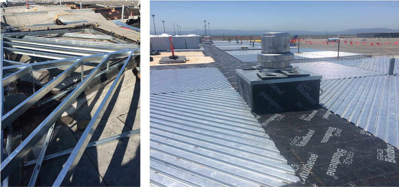
Figure 4. Shell infill – to the left is the installation of light gauge framing; it supports the metal decking shown on the right, creating a level roof plane. Courtesy of MWA Architects.
The original 48 hyperbolic paraboloid roof shells formed individual “inverted pyramids” supported by a column, resulting in an undulating roof plane where each shell had to be independently drained. One of the project goals was to create a “flat” roof with a global drainage plane to improve the roofing system’s reliability and simplify its maintenance. The original 1960 design accounted for ponding of water in each shell, and so the initial plan for the retrofit was to fill the shells with EPS and foam – within the ponding load allowance – and maintain distributed loading. When the roofing contractor advocated an alternate infill design consisting of a light gauge framing “lid” (Figure 4), R+C developed a detailed computer model to analyze the significantly different way in which this scheme applies loads to the shells. In-situ load testing was used to validate the analysis results.
Summary
Construction on this $85 million phased project started in mid-2014. The Port of Oakland moved into their office space in September of 2017 with the project substantially completed. The renovation and retrofit of Terminal 1 resulted in a sustainable approach to achieving the project’s objectives (since the demolition and replacement of the existing building were avoided), while at the same time affording continued operation of the security checkpoint.
Formal LEED certification under the USGBC LEED rating system for Commercial Interiors (v2) for improved sustainability is currently being pursued, and the project is on track to achieve a LEED Gold rating.■
Project Team
Owner: Port of Oakland, Oakland, CA
Structural Engineer: Rutherford + Chekene, Oakland/San Francisco, CA
Architect: MWA Architects, Oakland, CA
Associate Architect: YHLA Architects, Oakland, CA
Owner’s Construction Representative: Consolidated CM, Oakland, CA
General Contractor: Turner Construction, Oakland CA
Steel Fabricator: Olson Steel, San Leandro, CA
Casting Production Team: Cast Connex, Toronto, Canada and Bradken, Saint Joseph, MO