
Recent Research Findings
Thermal bridges occur when a component of high thermal conductivity causes excessive heat flow through the building insulation envelope. A large variety of conditions can cause thermal bridging, including cladding (shelf angles, grillage posts, canopy beams), metal wall studs, window mullions, and poor corner detailing. Thermal bridges through the envelope by structural steel frames are either linear penetrations, such as shelf angles, or point penetrations, such as cantilever beams or rooftop columns.
Bridging of structural steel penetrations can be particularly significant due to the high thermal conductivity of steel, which is roughly 1,500 times that of typical insulations, and the relatively large cross-sections passing through the envelope. Furthermore, many structural steel details which form thermal bridges are continuous around the building perimeter. The physical phenomenon is exacerbated by the building design process itself which involves a number of professionals with differing roles and responsibilities. Engineers, often mechanical engineers, responsible for envelope design and the elimination of heat loss and thermal bridging are not permitted to touch the structural framing, while structural engineers are not generally educated or consulted about thermal issues.
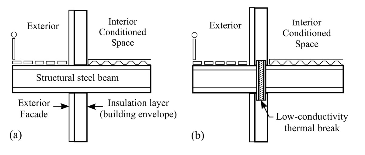
Example of a structural steel; a) thermal bridge and b) thermal break.
Thermal Breaks
One solution to bridging is to create a thermal break, whereby the structural member is “broken” by inserting a section of material with low thermal conductivity that is aligned with the insulation envelope. This solution is complicated by the strength of the thermal break materials which are generally inversely proportional to thermal conductivity. Finding the right balance between strength, stiffness, thermal conductivity, constructability, and economy is a challenge. In addition, the “broken” steel must be integrally connected to the building structural system, often requiring additional steel fasteners which act as thermal bridges themselves.
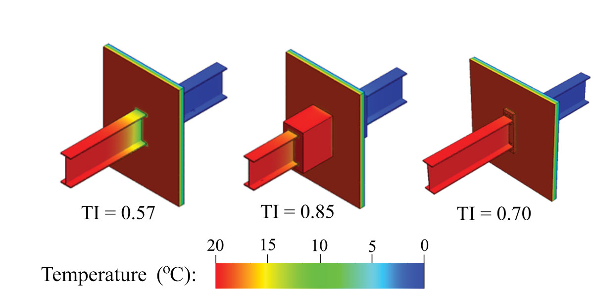
Effect of covering insulation and thermal break on the Temperature Index (TI) of a W-shape penetration.
Design and installation of structural thermal breaks are not currently addressed by code provisions in the United States; structural engineers have nonetheless begun applying thermal-break strategies. Despite prohibition by the Research Council on Structural Connection (RCSC), custom designed end-plate moment connections have been used that incorporate a low-conductivity pad/shim material such as wood, fiberglass, or fiber reinforced polymers (FRP) sandwiched between steel plates connected with bolts penetrating the assembly. Trends toward green construction and LEED certification have also prompted development and marketing of proprietary materials and products called Manufactured Structural Thermal Break Assemblies (MSTBA). MSTBA manufacturers generally also offer engineering services that provide capacities of the connections.
Covering Insulation and Condensation
Excessive heat flow and energy loss are not the only issues with thermal bridges. Localized regions of low temperature on interior steel surfaces can result in condensation from interior atmospheric humidity, leading to mold growth, staining, and ice or water damage. Meanwhile, the exterior surfaces may be hot enough to cause melting, resulting in ice damming, pooling water, and corrosion.
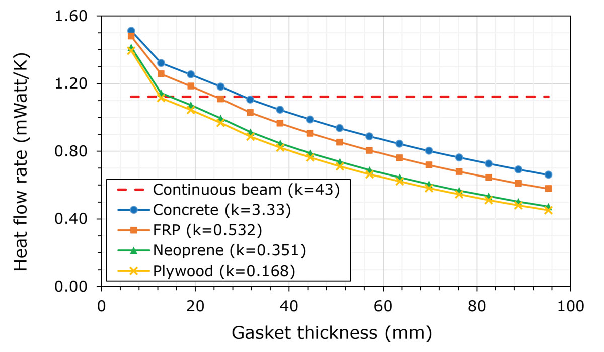
Comparison of heat flow rate and thermal-break pad thickness.
One method of evaluating the potential for condensation for a particular detail is by calculating its Temperature Index (TI). The Temperature Index is a European standard that compares the difference between the coldest inside surface temperature (obtained from simulation) and the outside air temperature with the temperature differential across the envelope. The temperature index is a dimensionless ratio that is independent of the temperature difference between the outside and inside air. ASHRAE has not yet codified a TI limit, but it has been suggested that 0.7 is an appropriate lower limit based on typical interior temperature and humidity.
Depending on climate, the price of heating fuel, the size and number of thermal-bridges, and the cost of creating thermal breaks, heat loss due to bridging may be an acceptable outcome. However, the damaging effects of condensation may not be. One method of mitigating condensation is “covering insulation,” insulation wrapped around the steel member surface on one or both sides of the bridge. While having only a minor effect on heat flow, covering insulation can drastically affect the condensation potential. The addition of covering insulation caused the TI of a continuous beam to increase from 0.57 to 0.85, while the addition of a thermal bridge only increased it to 0.70. However, little research has been conducted on covering insulation and more studies are necessary to determine its required length, thickness, and appropriate application situations.
Structural and Thermal Testing and Modelling
Two recent studies at the University of Alaska Anchorage (UAA) and Northeastern University (NEU) in Boston, MA, highlight the thermal and structural behavior of some common thermal-break strategies. Various thermal-break details were experimentally tested in a “Calibrated Hot-Box” to determine heat-flow and surface temperature characteristics, which were used to validate an extensive series of 3-D Finite-element thermal models. The models tested included various configurations of pad materials, thicknesses, and bolt materials.
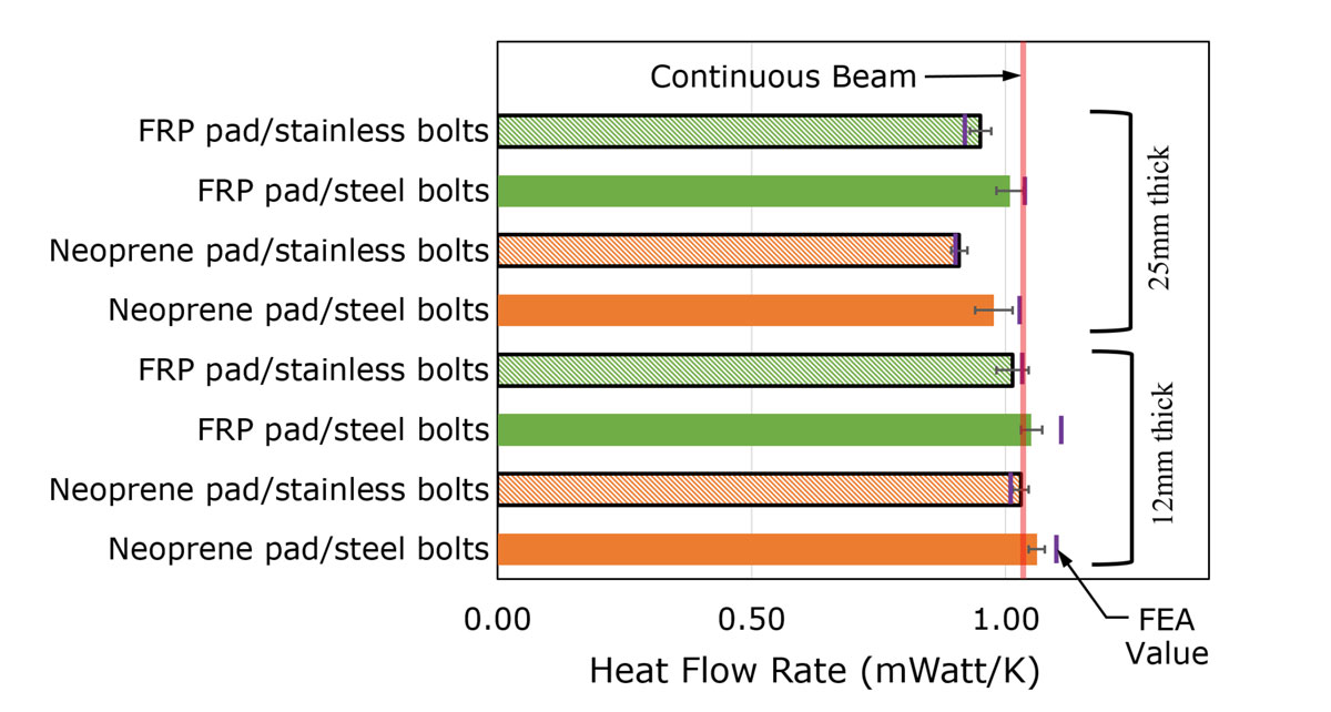
Results of heat flow tests in the calibrated hot box with various pad materials and thicknesses.
Representative results for thermal breaks with varying materials and thicknesses indicate that, despite the low thermal conductivity of the pads, the increased cross-sectional area of the connection and the penetrating bolts cause minor reductions in heat flow. For neoprene pad thicknesses of less than 25mm (1 inch), heat flow increases compared to a continuous penetrating member. Reasonable reduction in the heat flow does occur with relatively thick pads, greater than 76mm (3 inches). FRP shim pads reduce heat transfer through the building envelope across the range of pad materials considered, though the magnitude of improvement can vary significantly by type of thermal bridge and their connections to the structural system (continuous or discrete). Converting the bolts to stainless steel further reduces heat flow by 5% to 20%, with the bolt’s effectiveness increasing with pad thickness.
Structural testing at UAA indicated that neoprene pads, despite their prevalence in some regions, are inappropriate for use in structural connections. FRP pads, however, central to the NEU work, demonstrated very high strengths and stiffnesses as shims in snug-tight bolted connections. This research led to design recommendations for incorporating a range of shims in structural cladding details. These may be accessed via a report published by the Charles Pankow Foundation (www.pankowfoundation.org).
When to Use a Thermal Break
Designers must carefully consider the thermal conductivity and mechanical properties of the break, the structural application, and installation approach to adequately mitigate energy loss at the building envelope while maintaining the structural integrity of the connection. Test results show only a minor improvement for most common solutions. Test results also demonstrate that some details, while decreasing the potential for condensation, actually increases the overall heat flow through the detail when compared to the control condition with no thermal break.▪