
Practical Reinforced Concrete Building Design
Reinforced concrete (RC) shear walls are usually the primary lateral force resisting system for reinforced concrete buildings and adjacent shear wall piers are typically connected with coupling beams above doors or corridors at floor levels. The coupling beams reduce flexural moments in the coupled shear wall piers, provide an energy dissipation mechanism along the entire building height, and improve shear wall system efficiency.
As one of the most critical members in RC buildings, coupling beams should exhibit excellent energy dissipation capacity with only modest stiffness and strength degradation under cyclic loading. Good ductile hysteretic performance is usually achieved by providing sophisticated detailing, which induces construction difficulties. By varying rebar layout schemes and exploring different materials, various types of coupling beams are considered in searching for a balance between ductile hysteretic performance and construction practicality.
Currently there are five commonly-used types of coupling beams which are adopted by building codes and the design industry:
- Conventional RC coupling beams
- Diagonally-Reinforced concrete coupling beams
- Steel coupling beams
- Encased steel composite coupling beams
- Embedded steel plate composite coupling beams
Conventional RC Coupling Beams
Conventional RC coupling beams refer to coupling beams reinforced with horizontal rebars and closely-spaced stirrups. The design and detailing requirements for conventional RC coupling beams are the same as those for RC special moment frame members and are well provisioned in building codes, such as ACI 318 (Figure 1). Due to its relatively simple detailing and ease of construction, the conventional RC coupling beam is the most extensively used coupling beam type in building design. In low seismic risk areas, conventional RC coupling beam are sometimes sized wider than the connecting shear wall piers in flat-slab buildings.

Figure 1. Typical conventional concrete coupling beam.
However, the conventional RC coupling beam does not preserve good energy dissipation capacities under high cyclic shear stresses and significant pinching phenomena present in its hysteresis response. Diagonal shear failure and sliding shear failure are not avoidable in this type of coupling beam even with closely-spaced transverse reinforcing detailing. Research indicates that conventional RC coupling beams only exhibit satisfactory performance when the nominal gross section shear stress is below 3√f´c (psi) and when the beam behavior is flexure-controlled, although the nominal maximum allowable shear stress limit is 10√f´c (psi) in ACI 318.
Diagonally-Reinforced Concrete Coupling Beams
In the 1960s, a diagonal rebar layout in concrete coupling beams was proposed to effectively arrest the coupling beam sliding shear failure at the face of the coupled shear wall piers (Figure 2). To date, the diagonally-reinforced concrete coupling beams are recognized as the most effective type of reinforcing details to provide ductile performance with excellent energy dissipation capacity, especially when the span/depth ratio is less than 2. The well-established design provisions and details for diagonally-reinforced coupling beams can be found in the Section 18.10.7 of ACI 318-14, Building Code Requirements for Structural Concrete.

Figure 2. Typical diagonally-reinforced concrete coupling beam with full confinement.
In the design of a diagonally-reinforced concrete coupling beam, the shear forces are resisted by the diagonal rebars only and the moment capacities are automatically provided by the diagonal “truss” members. The nominal maximum allowable beam shear stress limit, 10√f´c (psi), is capped to ensure the coupling beam ductility and deformability.
Although diagonally-reinforced coupling beams exhibit excellent stiffness and highly-ductile energy dissipation capacities, there are some constructionability issues that limit their application:
- The practical width of diagonally-reinforced concrete coupling beams is at least 14 inches (16 inches or more is preferable) to accommodate all reinforcement meeting the minimum code-allowed spacing requirements.
- The on-site placement of diagonal reinforcement is difficult and labor-intensive.
- The effectiveness of diagonal reinforcement decreases significantly when the span-to-depth ratio is larger than 2 and the diagonal rebar inclination angle becomes small, while most architecturally practical coupling beam dimensions in high-rise buildings fall in this range.
Steel and Encased Steel Composite Coupling Beams
Steel coupling beams and encased steel composite coupling beams are used as viable alternatives to avoid the construction difficulties inherent in diagonally-reinforced concrete coupling beams. The steel members for the two coupling beam types are implicitly wide-flange steel members, although steel tubes were also used in early research (Figure 3). Extensive experiments indicate that both steel coupling beams and encased steel composite coupling beams can provide excellent ductility and energy dissipation capacities, which are comparable to those of diagonally-reinforced concrete coupling beams. ANSI/AISC 341-16, Seismic Provisions for Structural Steel Buildings, adopts both types of coupling beams in composite shear wall systems with design and detailing provisions.
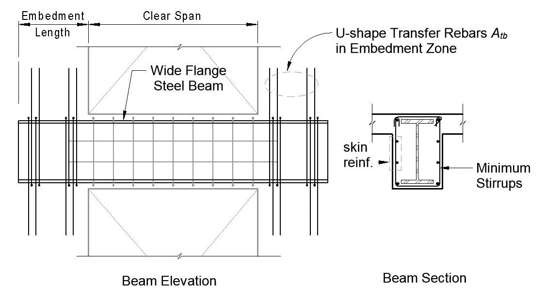
Figure 3. Typical encased steel composite coupling beam.
For these two types of coupling beams, both shear forces and flexural moments are assumed to be entirely resisted by the steel member. The benefits of the concrete encasement are currently ignored due to a lack of data. The concrete encasement provides higher beam stiffness and acts as a fire proofing layer for the encased steel beams.
Different from reinforced concrete coupling beams, the code-specified maximum allowable shear stress limit for concrete beams (e.g. 10√f´c (psi) in ACI 318) can be relieved for the encased steel composite coupling beam. Although no research on the interaction between the steel member and the RC concrete encasement is carried out, a practical size range of the steel beam to the coupling beam should be maintained to ensure the appropriate composite action of the encased steel composite coupling beam. Similarly, a maximum allowable nominal shear stress limit for the encased steel composite coupling beam is desirable for concrete encasement cracking control, while no value is yet available in the literature.
The most important item in the design of steel coupling beams and encased steel composite coupling beams is the embedment of the steel members. The embedment length design of these two types of coupling beams is usually based on the rigid Mattock-Gaafar embedment model by satisfying the expected coupling beam-shear wall connection shear strength (Eq. H4.1 & H5.1 in AISC 341-16). Appropriate detailing along the clear span and the embedment regions of the coupling beams are important as well for ductile performance and good energy dissipation capacity.
Compared to the diagonally-reinforced concrete coupling beam, the construction of the steel/encased steel composite coupling beam is much more feasible and the disturbance of the construction schedule can be negligible once the contractor becomes familiar with the construction procedure. However, the wide flange steel members tend to interfere with vertical and confinement reinforcement in the coupled shear wall piers, especially those in the boundary element zones of special shear wall systems. To accommodate both the shear wall rebar detailing requirements and steel beam embedment, wider or barbell-shaped wall piers and special detailing must be used. The practice of coping the steel beam flange is not recommended since reducing the flange width will increase the steel beam embedment length and may result in defects in the protected zone of the encased steel composite coupling beam. Further, embedded steel members complicate any sleeves that may run laterally through the coupling beam, often required for sprinklers.
Embedded Steel Plate Composite Coupling Beam
To alleviate the conflict between steel members and shear wall reinforcement, designers can consider the use of embedded steel plate composite coupling beams. As shown in Figure 4, headed studs are welded to both vertical faces of the steel plate in a typical embedded steel plate composite coupling beam and pose much less disturbance to shear wall vertical reinforcement, although special detailing is still needed for the horizontal/confinement rebars. The headed studs are necessary to provide appropriate anchorage and transfer forces between the concrete portion and the steel plate. Research indicates that the presence of the steel plates can effectively hinder the development of diagonal cracks and prevent brittle failures of concrete coupling beams, and the embedded steel plate composite coupling beam exhibits much better ductile performance and deformability than comparable conventional RC coupling beams.

Figure 4. Typical embedded steel plate composite coupling beam.
Similar to the encased steel composite coupling beam, proper embedment design of the steel plate is critical to ensure good ductile performance of this type of coupling beam. The rigid Mattock-Gaafar embedment model can be used to determine the embedment length of the embedded steel plate by assuming uniform bearing stress from steel plate and headed studs.
In the capacity design of this composite coupling beam, contributions from both the concrete and steel plate need to be considered. The steel plate is used to supplement the capacities of the reinforced concrete section. Considering the different strain distributions in the RC concrete portion and the steel plate due to their interaction, Su & Lam (2009) proposed a unified design approach for this type of coupling beam. The design rules of thumb are: (a) the ratio of the steel plate depth over the composite coupling beam depth should be limited to be 0.8~0.95; (b) the practical span-to-depth ratio range is 1.0~4.0; (c) minimum shear reinforcement must be provided; (d) minimum embedment length is dependent on coupling beam span/depth ratio and can vary from 0.35~0.7 times of the beam clear span; (e) The maximum nominal shear stress of the composite coupling beam is capped to be 1.5√fcu Mpa (18√f´c psi), and the shear force resisted by the steel plate should be less than 0.45Vu, which limits the use of this coupling beam.
Beam Stiffness Reduction
Under the current strength-based design framework, building analysis and design are predominantly carried out based on linear elastic structural models. Considering the effect of beam cracking, rebar slippage, and steel member fixity point location, reduced coupling beam stiffnesses are suggested in elastic building models depending on the coupling beam types:
- Conventional RC coupling beams and diagonally-reinforced concrete coupling beams – ACI 318 specifies 0.35 beam stiffness reduction factor for the ultimate design, which is a well-accepted design industry practice.
- Steel coupling beam – Elastic effective bending stiffness for ultimate design is reduced to be 60% of the original value due to steel beam effective fixity point (AISC 341-16):
(EI)eff = 0.6EsIsteel - Encased steel composite coupling beam – Elastic effective bending stiffness for ultimate design was suggested as (Motter et. al, 2017):
(EI)eff = 0.06 • ln/h • EsItrans
In which ln/h is the beam span-to-depth ratio and Itrans is the transformed moment of inertia of the encased steel composite coupling beam. However, this formula will lead to small stiffness values when the span-to-depth ratio is small. Following industry practice, 0.35EcIg can be used as the lower bound for this kind of coupling beam in building analysis. - Embedded steel plate coupling beam – To date, no formula has been explicitly proposed for the effective bending stiffness of the embedded steel plate coupling beam. Experiments indicate that the stiffness difference between the embedded steel plate coupling beam and the associated conventional RC coupling beam is not significant (Su & Lam, 2009), therefore 0.35EcIg is a reasonable reduced stiffness value for the embedded steel plate composite coupling beam ultimate design.
For both steel coupling beams and the encased steel composite coupling beams, the effective bending stiffness needs to be adjusted through iteration since the steel member size is unknown until designed.
Beam Shear Force Vertical Distribution
In high-rise building design, engineers often apply controlling beam design results to multiple floors, avoiding minor changes on a story-to-story basis, i.e. the coupling beam design reinforcements are “grouped” for multiple adjacent floors depending on the variation of beam design shear forces over the building height. Designers may also justify a redistribution of overstressed beams to understressed beams above and below to alleviate rebar congestion. This practice is equivalent to using smaller effective stiffness for coupling beams in analysis and whether it is allowable depends on the ductility and deformability of the coupling beam types.
For conventional RC coupling beams, the deformability and ductility are poor when the beam is under high cyclic shear stress; therefore, shear force vertical redistribution is not recommended. While the other four types of coupling beams exhibit much better ductility and deformability, the lower bound of coupling beam stiffness or shear force vertical distribution can be reasonably applied in building design during the process of designing coupling beams in order to alleviate rebar congestion. For steel coupling beams and encased steel composite coupling beams, AISC 341-16 explicitly permits shear force vertical distribution up to 20%.
Summary

Table summary of the five types of coupling beams in RC buildings.
Each of the five types of coupling beams adopted by the industry has its own benefits and limitations, as summarized in the Table. Still, not one single type of coupling beam is applicable to all cases in building design. The conventional RC coupling beam is often the most feasible and economical coupling beam whenever the beam shear stress is low and the beam is flexure controlled. When coupling beam span-to-depth ratios are small and high shear stresses are expected, the other four types of coupling beams should be explored. The limitations of these types of coupling beams and the associated anchorage requirement should be kept in mind to choose an appropriate coupling beam type for specific projects. As always, the designer should consider the preferences of the construction team whenever possible, as many contractors will have varying opinions related to each methodology.■
References
ACI 318, Building Code Requirements for Structural Concrete and Commentary, ACI Committee 318, American Concrete Institute, Farmington Hills, MI, 2014
AISC, Seismic Provisions for Structural Steel Buildings, ANSI/AISC 341-16, Chicago, 2016
K.A. Harries, B.N. Gong, B.M. Shahrooz, Behavior and Design of Reinforced Concrete, Steel, and Steel-Concrete Coupling Beams, Earthquake Spectra, Vol. 16 (4), 2000, 775-799
J.P. Moehle, T. Ghodsi, J.D. Hooper, D.C. Fields, R. Gedhada, Seismic Design of Cast-in-place Concrete Special Structural Walls and Coupling Beams, A Guide for Practicing Engineers, NIST GCR 11-917-11Rev-1, NEHRP Seismic Design Technical Brief No. 6., 2011, pp 37
C.J. Motter, D.C. Fields, J.D. Hooper, R. Klemencic, J.W. Wallace, Steel-Reinforced Concrete Coupling Beams II: Modeling, Journal of Structural Engineering, ASCE, Vol.143 (3), 2017
R.K.L. Su, W.Y. Lam, A Unified Design Approach for Plate-Reinforced Composite Coupling Beams, Journal of Construction Steel Research, Vol. 65 (3), 2009, 675-686