
Part 2: Settlement Profile Convergence Method
In Part 1 (STRUCTURE, November 2018) of this 2-part series, the definition of the modulus of subgrade reaction was presented and the current state of design with regard to its use was discussed. That article further described some potential shortcomings of the simplified theory of subgrade reaction. This article continues to describe the settlement profile convergence method and how it can be implemented into a new design.
Distribution of Ks
As much as the value of Ks is important, distribution of Ks and its effect on foundation design is even more important. It is a complex subject and often not used for routine foundation design because of the non-availability of any simple mechanism. For large scale projects, engineers often collaborate and use sophisticated software for soil-structure-interaction.
From the theory of subgrade reaction, we know that the settlement profile of a uniformly loaded flexible foundation takes the shape of a bowl or trough. Does this hold for a supporting soil medium having uniform Ks? We can begin with a simple case study using a standard commercial software package.
Modeling
Mat geometry: Square Mat 12 x 12 x 0.5 feet
Soil Bearing Capacity: 4 kip/ft²
Loading: 1 kip/ft²
Solution
Ks can be estimated as,
![]()
where, I = Safety factor = 3.0, qa (assumed) is the allowable bearing capacity (given 4.0 kip/ft²), δ is the allowable soil settlement = 1 inch (assumed)
As discussed earlier, the displacement profile is expected to take the shape of a bowl or trough. However, the foundation settled uniformly (Figure 5), which did not match our expected behavior.
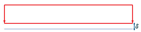
Figure 5. Vertical deflection diagram of the uniformly loaded mat foundation.
It is hardly a surprise. We know, for a uniformly loaded mat, subgrade reaction increases from the center towards the edge and, as a result, the foundation displacement profile takes the shape of a bowl. For this solution, a constant Ks value was used (which is often the practice for its simplicity) and, as a result, the program computed erroneous physical behavior.
Extending the Current Practice
Fortunately, it is not too difficult to manipulate a computer program to get close to the expected physical behavior. We can extend the model to create varying soil medium from the center of the foundation towards the edge. In other words, we can use a variable Ks to depict the desired settlement profile of the supporting soil medium.
Solution
As shown in Figure 6, divide the supporting soil medium into several bands (five for this example). Also, assume subgrade reaction increases as much as 100% from the center towards the edge.
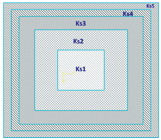
Figure 6: Banded Ks distribution from lowest at the center to the highest towards the edge.
Ks1 = 0.0833 kip/in2/in
Ks2 = 0.09996 kip/in2/in
Ks3 = 0.119952 kip/in2/in
Ks4 = 0.143942 kip/in2/in
Ks5 = 0.172731 kip/in2/in
After running the analysis, the deflection profile takes the shape of a bowl or trough and matches the expected soil settlement profile (Figure 7). Also, it is interesting to notice the soil pressure contour. Unlike the case for a uniform Ks, the base pressure contour now shows varying pressure from the center towards the edge (Figure 8).
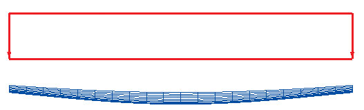
Figure 7: Displacement profile of the mat foundation when using distributed Ks.
So, it is natural to conclude that a flexible mat foundation should always be analyzed using variable moduli of subgrade reaction. It predicts more accurate physical behavior and, hence, the results should be more accurate.
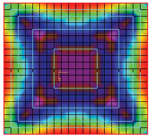
Figure 8: Base pressure contour of the mat foundation when using distributed Ks.
NCNB Corporate Center
Variable Ks was used for the second NCNB (Horvilleur and Patel) study, which varied from the lowest value (181 psi/in) at the centroid to the highest value (548 psi/in) at the edge. As expected, the researchers observed a dishing phenomenon. The two analyses were compared (uniform Ks at 290 psi/in and a variable Ks). Variation in soil pressure was around 11%, which may not be that significant. However, the differences in moment was significant, varying as much as 120%.
Iterative Method
It is evident that the use of a variable Ks is better than using a uniform Ks. However, the value of Ks depends on many factors including rigidity of the foundation, soil stiffness, and settlement.
As an example, initial estimated values of Ks for a given zone were derived based on a predicted settlement. After finite element analysis, calculated displacement for a given zone (more precisely for a given node) may not match with the predicted displacement. So, a new Ks value should be calculated and the analysis rerun. This iterative process should continue until the solution converges.
Discrete Area Method
The Discrete Area Method (Ulrich) is an iterative method to achieve deflection compatibility between mat deflection and soil settlement. The steps are described as:
- Create a finite element model for a mat foundation and analyze it using a geotechnical engineer’s best estimated uniform Ks value.
- Using base pressure from step 1, the geotechnical engineer calculates soil settlement at each node of the FEA model and a new set of Ks values at corresponding nodes.
- Input a new set of subgrade moduli in the structural finite element model and obtain a new pressure distribution and settlement.
- Using the pressure profile from step 3, the geotechnical engineer calculates settlement at each node and a corresponding Ks at each node.
Repeat step 3 and step 4 until convergence is achieved. This happens when the displacements predicted by the structural engineer’s finite element analysis match the settlements predicted by the geotechnical engineer. The resulting coefficient of subgrade modulus may differ significantly from the initial estimated values and, as a result, will significantly influence mat design. The convergence may require multiple iterations and, as the process cannot be automated, use of this method demands close collaboration between the structural and geotechnical engineers.
A New Approach
Base pressure, settlement, stiffness, and modulus of subgrade reaction are all intertwined. Dependency among these parameters adds to the complexity and makes it difficult to achieve a quick, definitive solution.
A new computer-based approach has been developed and proposed by the author, the Settlement Profile Convergence Method. It is an iterative solution to converge estimates of foundation displacement and soil settlement. The most critical aspects of the solution are the initial estimation of soil settlement and normalization of the settlement profile. This minimizes the effect of various factors used in different proposed equations for soil stress calculation.
The steps are described as:
- Generate a mesh to create a finite element analytical model of the foundation slab.
- Use the standard Boussinesq’s equation, or any other method, to calculate soil stress under each meshed node for a given loading.
- Normalize settlement values between 1 and the ratio between maximum over minimum settlement.
- Calculate Ks for each node from allowable bearing capacity and the calculated soil settlement from step 3.
- Calculate nodal spring constants by multiplying Ks with the nodal tributary area. Assign spring constants as compression-only springs.
- Run the finite element analysis.
- Extract nodal displacement values from the analysis.
- Repeat step 3 through step 7.
- Compare the new displacement profile with the displacement profile from the last analysis.
- Repeat steps 8 and 9 until two consecutive analyses converge or fall within a reasonable tolerance limit.
Effectiveness of the New Method
The new method is significant for several reasons.
- It focuses on the shape and relative displacements rather than the absolute displacements, which minimizes the effect of initially estimated soil settlement.
- The process is automated and complementary to the current FEA based mat foundation analysis.
- It considers structural rigidity.

Figure 9: Revised displacement diagram from Settlement Profile Convergence Method.

We can compare the example from the earlier section, Distribution of Ks, to the Settlement Profile Convergence Method, studying the new method’s effectiveness. As expected, the displacement profile from both the methods takes the shape of a bowl (Figure 9). However, the shape produced by the Settlement Profile Convergence Method is smooth. It is even more apparent from the resulting base pressure diagrams from each analysis. As discussed earlier, Ks is expected to vary radially from the center towards the corner. The resulting contour diagram (Figure 10) correctly depicts that expected radial distribution. It is a significant improvement over any existing method.
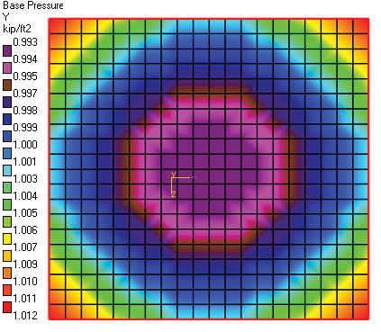
Figure 10: Revised base pressure contour for 0.5-foot thick mat foundation.
Conclusion
A computer program can be developed to use the Settlement Profile Convergence Method effectively. It is an iterative solution; the total solution time will extend marginally. However, as it depicts the physical behavior more closely, the final results are expected to be more accurate. Current practice is not necessarily conservative. It is over-simplified and can be erroneous. Soil-structure interaction is a complex subject, and this new method is an additional tool at the engineer’s disposal for automating a foundation analysis. It does not replace engineering judgment or experience. Close collaboration among structural and geotechnical engineers is highly recommended for the best possible outcome.■
References
Terzaghi, Peck, Mesri. (1996). Soil Mechanics in Engineering Practice (Third Edition). Brentwood, CA. John Wiley & Sons.
Braja M Das. (1983). Advanced Soil Mechanics (International Edition) Washington. Hemisphere Publishing Corporation.
Joseph E. Bowles. (1996). Foundation Analysis and Design (Fifth Edition) New York City. McGraw-Hill.
F. Horvilleur, V. B. Patel. Mat Foundation Design. (1995). A Soil-Structure Interaction Problem. ACI SP-152-3.
J. Ulrich, Jr. (1995) Subgrade reaction in mat foundation design. ACI SP-152-4. Apurba Tribedi. Correlation between Soil Bearing Capacity and Modulus of Subgrade Reaction. STRUCTURE, December 2013.