
The design provisions for the shear strength of steel-to-steel screw connections provided by Section E4.3 of the North American Specification for the Design of Cold-Formed Steel Structural Members, AISI S100-12, are based on testing. The test specimens were typically steel sheets in contact with each other with no other material or significant gap between the steel components. However, screw connections are often fabricated such that there is material or a gap within the connection. For example, where continuity of the sheathing is desired, attachment of ledger track to wall studs will have the gypsum wallboard within the connection or attachment of the exterior sheeting to the roof or wall structural members will have insulation material within the connection. Thus, a connection may have an intended or unintended gap between the steel components.
There is minimal test data for screw connections having other materials or intended gaps between the plies of a steel-to-steel connection. Thus, the engineer is often left without clear guidance on how to comply with AISI S240 Section C4.1.2.2, which states that, “Screw fasteners shall penetrate individual components of connections without causing permanent separation between components.”
The objective of this article is to summarize available test data and provide design guidance based on that data.
Behavior and Limit States
Screw connections that transfer shear forces may fail by three possible limit states – bearing, tilting-tearing, or shear of the screw. The presence of a gap or separation of the steel sheets would likely have little effect on the bearing capacity of a screw connection. However, the presence of a separation may impact the tilting-tearing connection capacity and the screw strength.
Screw Strength
Research by Bambach and Rasmussen (2007) developed the following design equation for the nominal shear strength of a screw, Pns, as a function of the separation distance, dsep,
Pns = Pss (1 – dsep/2d)
Where, d = the nominal screw diameter and Pss = nominal shear strength of the screw as reported by the manufacturer or determined by independent testing. The research is based on the following parameter limits: 0.21≤ nominal screw diameter (in inches) ≤ 0.26, 0.31≤ sheet thickness (in inches) ≤ 0.79, 36 ≤ yield strength (ksi) ≤ 65, and dsep ≤ 0.31 inches. Although the researchers suggest limiting the Pns equation to the test program limits, it is suggested, lacking other data, that the equation may be used for other applications.
Tilting-Tearing Failure Mode
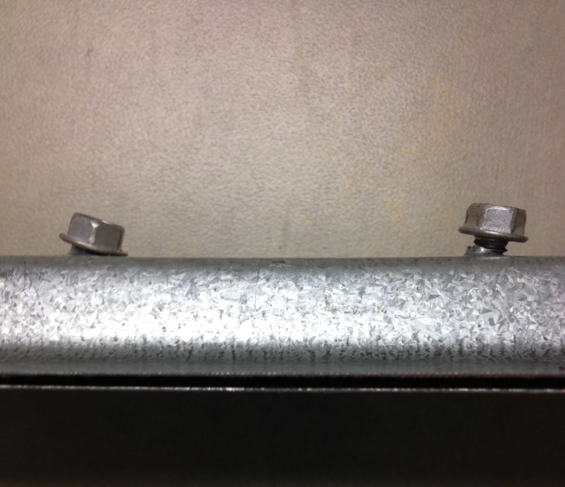
Figure 1. Screw tilting.
The tilting-tearing failure mode results in the fasteners tilting (tipping) when subjected to a shear force, as shown in Figure 1. Also, note that the plies of the connection may separate (Figure 1). Figure 2 also illustrates the tilting effect of the screws and the separation of the steel plies at failure.
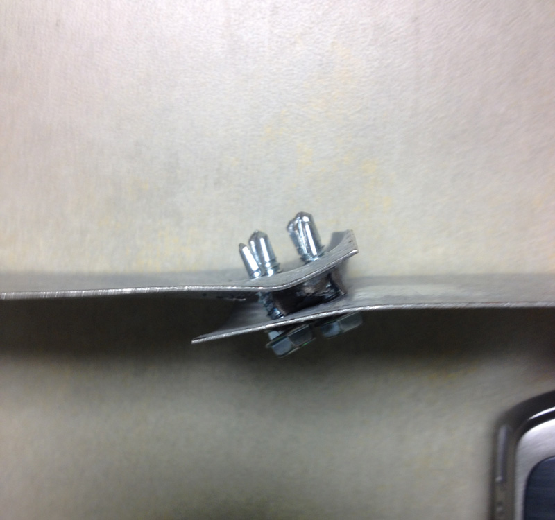
Figure 2. Separation of connection components.
As the length of the screw and distance between the connected elements increases, this failure mode becomes more critical. A review of the engineering literature provided test data from three experimental programs. The following is a summary of the three test programs.
A Virginia Tech study by Lease and Easterling (2006) performed 435 tests on single shear screw connections. The focus of the study was to determine the behavior of a screw connection when a blanket of compressed fiberglass insulation was present within the screw connection. The researchers suggested that a 0.85 factor could be applied to the nominal strength equations of AISI S100 Section E4.3 to achieve a better correlation of the test data to nominal strength calculation. However, they went on to conclude that no reduction was needed because the resistance factors fell within the range of the resistance factors of past research on steel-to-steel connections. A review of the data does indicate that, for a gap distance between the plies equal to or less than 0.15 inches, no modification factor may be required.
The International Seismic Application Technology (2009) analyzed data generated by a RAM Tech test program that focused on the behavior of screw connections in which gypsum wallboard was attached to a 43-mil steel sheet to simulate the attachment to a cold-formed steel wall stud. Tests were performed with either one layer of 5⁄8-inch gypsum or two layers of 5⁄8-inch gypsum to assess the impact of the gypsum wallboard. The intent was to simulate a one-hour and two-hour fire rated wall application. A ¼-inch-diameter self-drilling screw was used for all tests. A comparison of the test failure load to the AISI S100 Section E4.3 nominal strength, Pn, is summarized in Table 1.
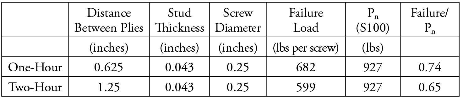
Table 1. Comparison of test failure load to AISI S100 Section E4.3 (ASAT, 2009).
A Steel Framing Alliance (2010) report summarizes the results of a test program that studied the screw connection strength when rigid foam insulation was present within the screw connection. Distances between the plies, ranging from one to four inches, were present in the test specimens. In this case, the distance between the plies was the thickness of the rigid foam insulation. A comparison of the test failure load to the AISI S100 Section E4.3 nominal strength, Pn, is summarized in Table 2.
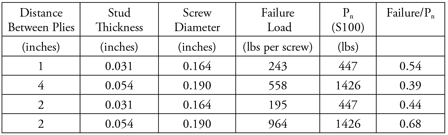
Table 2. Comparison of test failure load to AISI S100 Section E4.3 (SFA, 2010).
Interpretation and Recommendation
There is a clear trend that, as the distance between the plies increased, the connection strength decreased as illustrated in Figure 3 (although the data is limited). The reduction factor shown in Figure 3 is the ratio of Failure/Pn.
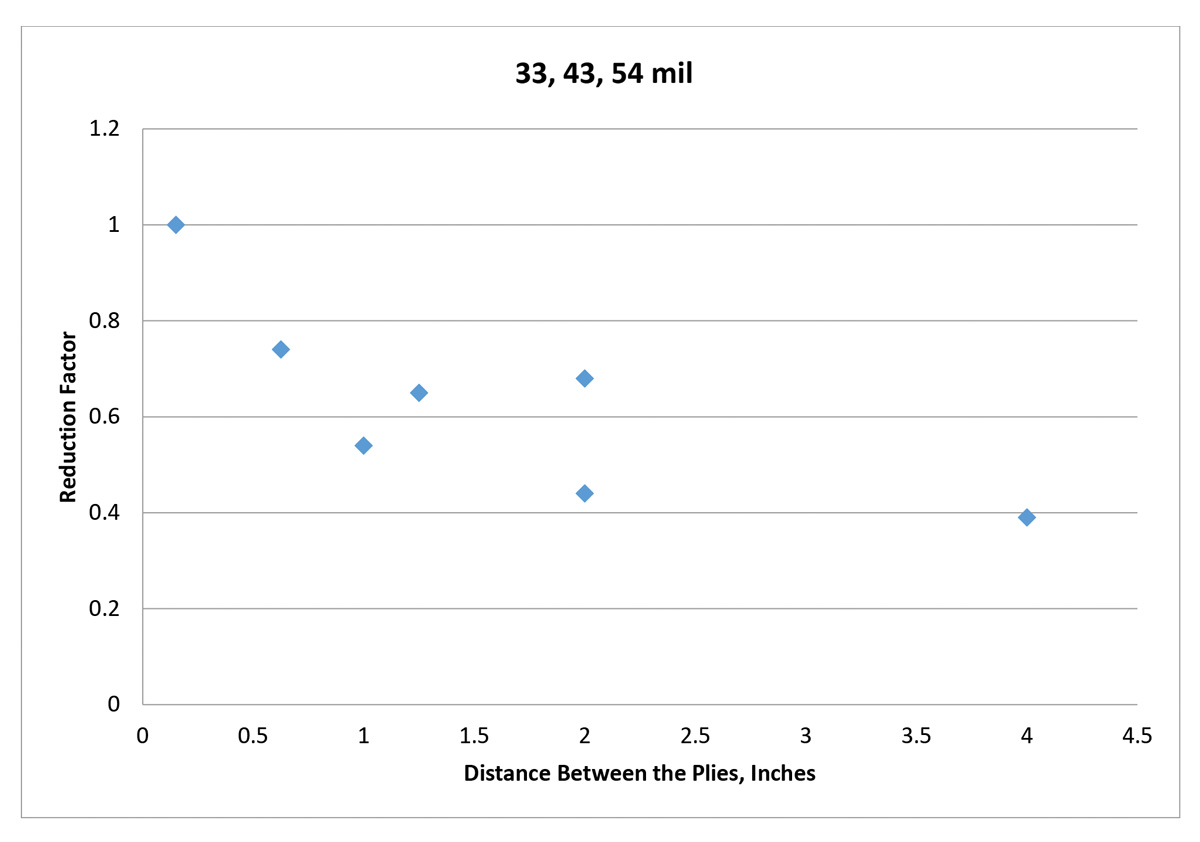
Figure 3. Ratio of failure to Pn.
Figure 3 indicates a trend; however, because the database is limited, a reduction factor equation is not being proposed. In addition, the strength and stiffness of the material between the plies are also likely an influencing factor for the potential reduction in connection strength. There has been no specific testing for an intended air gap between the plies in the test specimens, although in some cases the test specimens experienced significant deformations or gaps prior to failure as illustrated in Figure 2. Thus, a small gap, for example, equal to the thickness of the thinnest ply, may be deemed acceptable.
It is suggested that, for design, the engineer may be guided by the test results as indicated in Table 3.
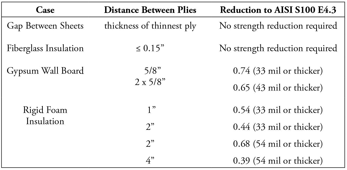
Table 3. General recommendations for distances between plies (based on test data).
Based on available test data, Table 3, along with AISI S100 design equations, offers design guidance for common gap conditions.
This article is based on a Cold-Formed Steel Engineers Institute Tech Note of a similar title (www.cfsei.org).▪