
161 Maiden Lane, New York, NY
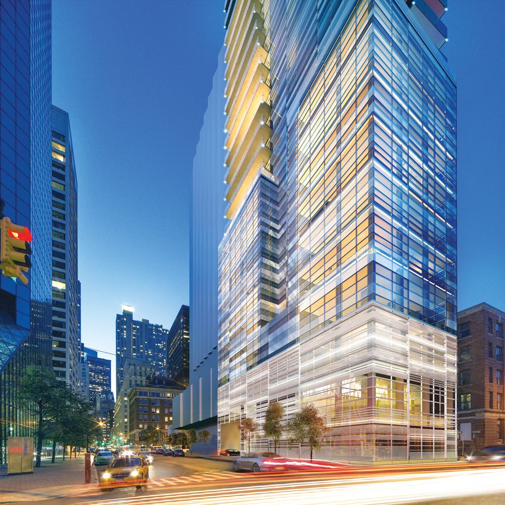
Currently under construction, Fortis Property Group’s One Seaport residential tower will become one of downtown Manhattan’s first residential skyscrapers directly fronting the East River. The slender tower, designed by Hill West Architects, will stand 57 stories high to a height of 662 feet above grade.
The structural system of the building consists of concrete flat plate construction and a reinforced concrete shear wall. Concrete strengths of up to 12 ksi were used to enhance strength and provide adequate stiffness. Additional lateral stiffness is provided by an outrigger and belt wall system that engages perimeter columns. This system provides flexibility in the architectural layout and increases structural efficiency.

Courtesy of Fortis Properties
Structural Challenges
Main challenges in the structural design include controlling lateral deflections, accelerations, and overturning of the structure due to wind forces and the building’s high aspect ratio (15+:1). In addition, foundation design considerations related to the depth of suitable substrate to support the high-rise tower were a concern. Pairing the high slenderness ratio together with deep foundation elements resulted in a structure which is much more flexible compared to the same building supported directly on typical Manhattan bedrock. A total of 4 tuned liquid dampers are incorporated to ensure occupancy comfort from dynamic motion and limit building accelerations.
Foundation Consideration
One Seaport’s site sits upon East River landfill that dates to the turn of the eighteenth century. With rock situated at 132 to 166 feet below grade, initial evaluations of deep foundation systems such as drilled piles and caissons, common to high-rise structures, were performed. The difficulties associated with drilling elements to such depths resulted in extremely high foundation bids from a limited number of contractors. An alternate system, not commonly utilized to support high-rise structures, was proposed. The solution used a jet-grout soil improvement system, to depths of 55 feet below grade, into the sand layer. WSP, geotechnical consultant RA Consultants, and specialty contractor Hayward Baker collaborated on the design and analysis of a soil improvement system that provided the strength and stiffness capable of supporting a reinforced concrete mat as the building’s foundation system.
Detailed Analysis and Challenges
Although the soil improvement system and foundation mat proved to be a cost-efficient system, there were design challenges due to the inherent stiffness of the system. Careful consideration and mitigation of the adverse effects were required throughout the design and construction phases for the tower to achieve the acceptable level of building performance under wind events. Variation of dynamic properties due to the effect of the foundation system were also included in the assessment of loads and induced vibrations during wind tunnel studies.
Due to the high winds along the eastern shoreline of lower Manhattan and the tower’s high slenderness ratio, the effect of overturning forces was a central focus in the analysis and design of the proposed tower. Nonlinear finite element analysis of the combined Superstructure-Foundation-Soil system for lateral and gravity loads indicated that lateral stiffness of the tower, and consequently its deformations and second-order effects, are highly dependent on the foundation system performance (Figure 1).
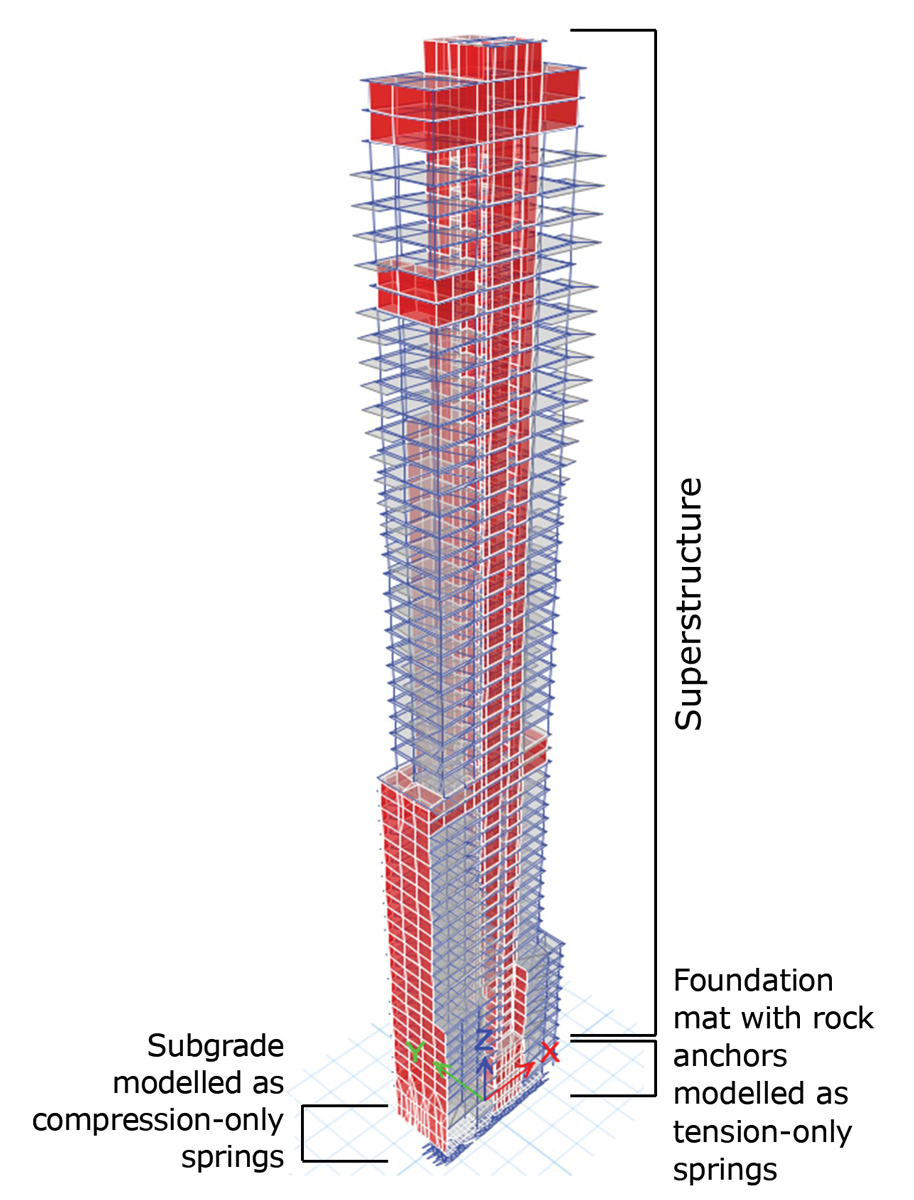
Figure 1. Global finite element model of superstructure-foundation-soil.
Uplift forces under the mat resulted in the use of +150-foot-long rock anchors with capacities of 580 kips (Figure 2). Detailed non-linear analyses were carried out to understand how the loss in pre-stress forces in the anchors, as a result of the settlement of the building, would affect the overall behavior of the tower under wind events. The four conditions studied, taking into consideration the phase of construction at which rock anchors are pre-tensioned, are:
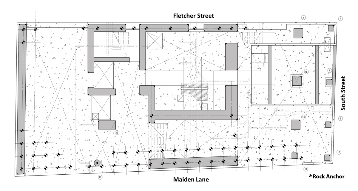
Figure 2. Layout of mat foundation.
- Condition 1 – foundation mat + rock anchors (100% loss of pre-tension). Under this condition, the axial deformation of the rock anchors would result in the largest building movement.
- Condition 2 – foundation mat + rock anchors (pre-tensioned, no losses considered). In this ideal condition, no axial deformation of the rock anchors would occur due to pre-stress forces in the anchors.
- Condition 3 – foundation mat + rock anchors (pre-tensioned, losses considered due to expected settlement). This condition represents a case where rock anchors are pre-stressed prior to construction of the superstructure.
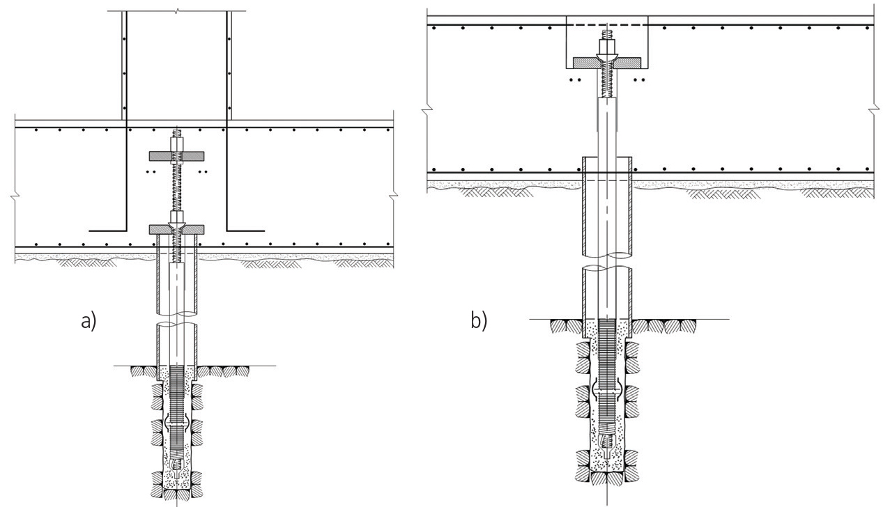
- Condition 4 – foundation mat + rock anchors (pre-tensioned, losses considered due to expected settlement, with accessible anchors re-tensioned). This condition represents when rock anchors which are accessible are re-stressed post construction of the superstructure (Figure 3).

Figure 3. Rock anchor details; a) Not accessible for re-tensioning; b) Accessible for re-tensioning.
Analysis Results
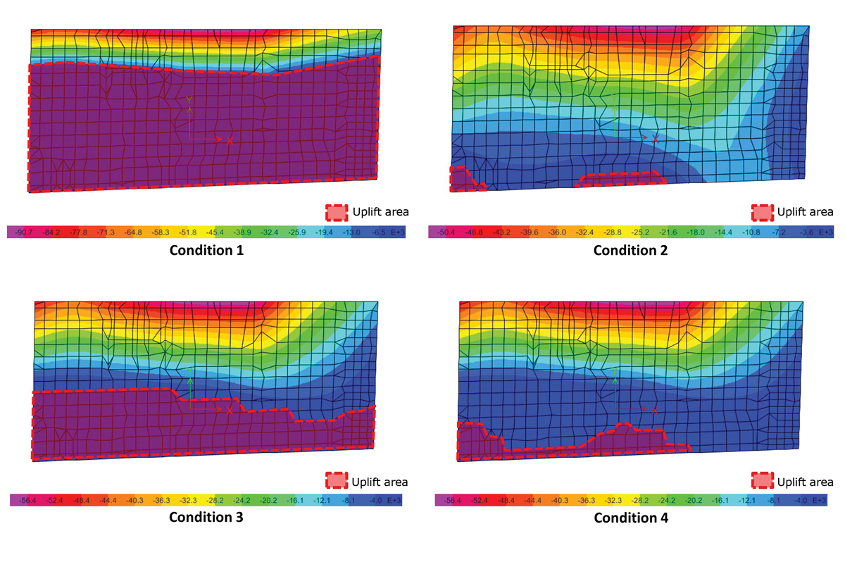
Figure 4. Distribution of soil pressure and location of uplift areas under mat foundation for gravity load and 700-year return-period wind load (Conditions 1 through 4).
The rotation of the mat and uplift were analyzed to understand the overall lateral movement of the tower. Figure 4 captures the portions of the mat which have uplift due to an ultimate level (700-year) design wind load for each of the four conditions studied. From the diagrams, it can be seen that the level of pre-tension forces in the anchors will play a significant role in the extent of the mat exposed to uplift, as a result of the rotation of the foundation mat and, hence, lateral movements and stiffness of the tower. Concomitant adverse effects of the mat rotations include a noticeable increase of tower deformations, as well as increased secondary effects, and are indicated in Figures 5 and 6. In comparison with an ideal fixed base condition, lateral deflections increase by 73% and secondary moments caused by P-Delta effects increase from 3% to 16% when all pre-tensioned forces are lost due to building settlement.
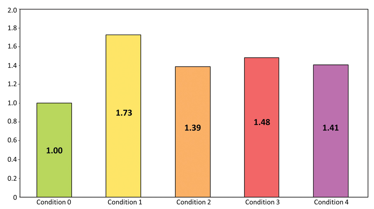
Figure 5. Top lateral displacement for 50-year return-period wind load normalized with respect to Condition 0 (fixed base).
Based on study results, final foundation system design was tuned to mitigate adverse effects of foundation flexibility on the tower’s global performance. The uplift area at the interface between foundation mat and underlying soil was sufficiently minimized, as shown in Figure 4 (Condition 4). The contribution of global P-Delta effects resulting in secondary moments was reduced to 5%. These factors, along with utilization of tuned sloshing dampers at the top of the tower, provided an efficient structural system within elegant and slender architectural form.
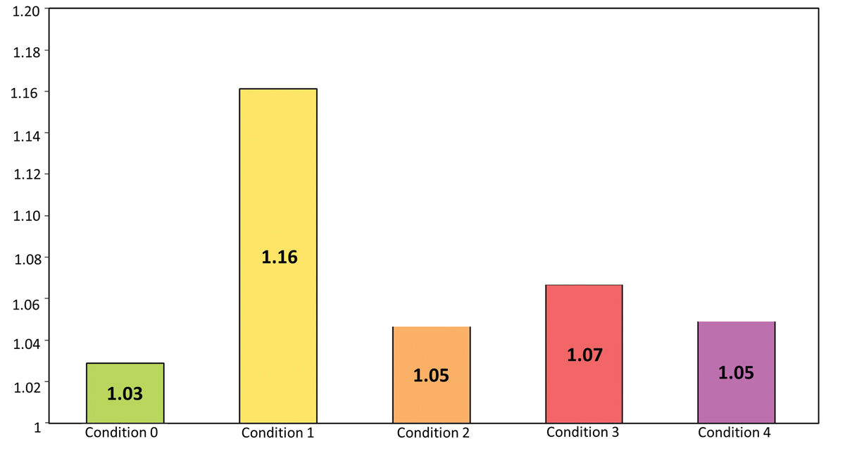
Figure 6. Ratio of base moment due to 700-year return-period wind load, considering P-Delta effects and foundation stiffness, to base moment without second-order effects.
Implementation of an alternative foundation system vetted by extensive nonlinear analysis of the combined Superstructure-Foundation-Soil system resulted in a sound structural solution for this high-performance residential tower located in downtown Manhattan. Moreover, the solution provided savings of approximately $6 million to the owner, Fortis Properties Group.▪