
Design for SDC D, E, and F Buildings
This article presents an overview of the design requirements for shallow reinforced concrete foundations (spread footings and mat foundations) supporting buildings assigned to Seismic Design Category (SDC) D, E, or F. Also included is a proposed design method that goes beyond requirements in current codes and standards. Although the following discussion focuses exclusively on spread footings supporting members of the seismic-force-resisting system (SFRS), it is also applicable to mat foundations.
According to ASCE/SEI 7-16, Minimum Design Loads and Associated Criteria for Buildings and Other Structures, Section 12.18.9.2, buildings are permitted to be supported on shallow foundations provided the foundations are designed and detailed in accordance with ASCE/SEI 12.13.9.2.1 and the conditions of ASCE/SEI 12.13.9.2 are met.
Determining Base Area
Bearing failure is the primary design consideration when footings are subjected to seismic forces. It is common practice to use service load combinations to size the footing with an allowable bearing capacity that is equal to the static bearing capacity multiplied by a factor to account for the transient nature of the earthquake forces. The 2018 International Building Code (IBC), Section 1806.1, permits the presumptive vertical and lateral bearing pressures values in Table 1806.2 to be increased by one-third where the alternative basic load combinations of IBC 1605.3.2 that include earthquake forces are used. It is also permitted in such cases to use allowable bearing capacities that have been determined from a geotechnical investigation.
ASCE/SEI 12.13 contains requirements for the design of foundations, including spread footings. In lieu of performing a linear analysis that includes foundation flexibility and the load-deformation characteristics of the foundation soil system (ASCE/SEI 12.13.3), the base dimensions of a footing can be determined utilizing either a strength design method (ASCE/SEI 12.13.5) or an allowable stress design method (ASCE/SEI 12.13.6).
Strength Design Method
In the strength design method, load combinations 1 through 7 in ASCE/SEI 2.3.1 and 2.3.6 are used with the seismic load effects, E, determined in accordance with ASCE/SEI 12.4.2:
- For use in load combination 6: E = Eh + Ev = ρQE + 0.2SDSD
- For use in load combination 7: E = Eh – Ev = ρQE – 0.2SDSD
In these equations, ρ is the redundancy factor determined in accordance with ASCE/SEI 12.3.4, SDS is the design spectral response acceleration at short periods, and QE are the effects due to the horizontal seismic forces.
The combined factored stresses at the base of the footing must be less than or equal to the design soil bearing strength, ϕQns. The resistance factor, ϕ, is given in ASCE/SEI Table 12.13-1 and is equal to 0.45 for bearing strength. ASCE/SEI 12.13.5.2 permits ϕ to be taken as 0.80 where the nominal bearing strength has been determined by in-situ testing of prototype foundations when the testing program has been approved by the authority having jurisdiction.
The nominal soil bearing strength, Qns, is permitted to be determined by the following methods:
- Presumptive load-bearing values (organic silts, organic clays, peat, or non-engineered fill are assumed not to have a presumptive load capacity).
- Geotechnical site investigations by a registered design professional, which include field and laboratory testing.
- In-situ testing of prototype foundations.
According to ASCE/SEI 12.13.5, overturning effects at the soil-foundation interface are permitted to be reduced by 25% in accordance with ASCE/SEI 12.13.4 for foundations of buildings where (1) the structure is designed in accordance with the Equivalent Lateral Force Procedure (ELFP) in ASCE/SEI 12.8 and (2) the structure is not an inverted pendulum or cantilevered column type structure. Only the seismic load effects may be reduced by 25% when calculating the bearing pressures; all other load effects must not be reduced. A 10% decrease of the overturning effects is permitted when a modal analysis in accordance with ASCE/SEI 12.9 is performed.
Analysis of bearing stresses using the strength design method depends on whether inelastic soil response is acceptable or not. If elastic response is required, the maximum factored bearing stress is calculated using the appropriate elastic equations in Figure 1 where factored axial forces, Pu, and bending moments, Mu, are determined by load combinations 1 through 7 in ASCE/SEI 2.3.1 and 2.3.6.
Where inelastic soil response is acceptable, the maximum bearing stress, which is assumed to be constant over the entire contact area, can be calculated assuming full plasticity of the soil (Figure 2).
qu,max = Pu/BL´
Regardless of elastic or inelastic soil response, the maximum bearing stress, qu,max, must be less than or equal to the design soil bearing strength, ϕQns. The area of the footing is determined based on the governing load combination and the appropriate equation for maximum factored bearing stress.
Allowable Stress Method
In the allowable stress design method, load combinations 1 through 10 in ASCE/SEI 2.4.1 and 2.4.5 are used with the seismic load effects, E, calculated in accordance with ASCE/SEI 12.4.2 to determine the maximum bearing stresses at the base of a footing, which must be less than or equal to the allowable bearing capacity. As in the case of the strength design method, reduction of foundation overturning effects is permitted in accordance with ASCE/SEI 12.13.4.
Proposed Design Method
The earthquake effects, E, determined in accordance with ASCE/SEI Chapter 12 are less than those that would be expected during a design-level earthquake. Therefore, in the case of footings, the reactions caused by E that are transferred from the supported member to the footing will typically be smaller than those that would be transferred during an actual seismic event. Thus, determining the bearing stresses (and the required flexural and shear strengths) based on code-prescribed earthquake forces inherently implies that some inelastic behavior is allowed in the footing regardless if strength-level or service-level load combinations are used. Allowing such inelastic behavior may be tolerable for typical buildings assigned to nonessential risk categories (ASCE/SEI Table 1.5-1). However, foundations that are designed in this way may possibly be damaged during a seismic event, and may not perform as intended during subsequent seismic events. Furthermore, inspecting foundations after an earthquake can be very expensive or might not even be possible, so there is usually no direct way of ascertaining if damage has occurred unless the damage is obvious. Repairing foundations is also costly and, in some cases, may not be feasible.
For buildings assigned to SDC D, E, and F, it is recommended to design footings using load combinations 1 through 7 in ASCE/SEI 2.3.1 and 2.3.6, where load combinations 6 and 7 include seismic load effect with overstrength:
- Load combination 6: 1.2D + Ev + Emh + L + 0.2S = (1.2 + 0.2SDS)D + ΩoQE + L + 0.2S
- Load combination 7: 0.9D – Ev + Emh = (0.9 – 0.2SDS ) + ΩoQE
In these equations, Ωo is the overstrength factor given in ASCE/SEI Table 12.2-1 for the SFRS.
Like the design of collectors in accordance with current provisions, footings are anticipated to respond primarily in the elastic range when designed using this approach, thereby reducing the likelihood of damage when subjected to a design-level seismic event. Nonlinear response is limited to the supported members, which are correctly detailed according to the appropriate requirements in ACI 318-14, Building Code Requirements for Structural Concrete, Chapter 18. As an upper limit, the forces delivered to a footing need not exceed the capacity of the supported structure.
Design Procedure
The following design procedure can be used to size the base area of a footing supporting members that are part of the SFRS in buildings assigned to SDC D, E, or F:
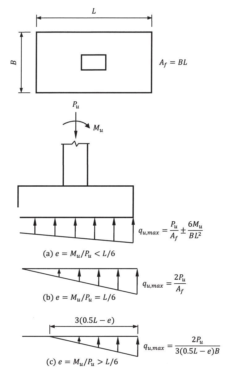
Figure 1. Soil pressure distributions beneath a footing subjected to axial force and bending moment.
- Determine the factored load effects using load combinations 1 through 7 in ASCE/SEI 2.3.1 and 2.3.6, where load combinations 6 and 7 include seismic load effect with overstrength.
- Where elastic soil response is required, determine the base area of the footing, Af, using the appropriate elastic equations in Figure 1 and the design soil bearing strength, ϕQns.
- Where inelastic soil response is permitted, determine the base area of the footing, Af, using the uniform bearing pressure distribution illustrated in Figure 2 and the design soil bearing strength, ϕQns.
Resistance to Lateral Loads
In general, lateral forces from earthquakes are transferred from a footing to the adjoining soil through friction at the base of the footing and passive bearing pressure along the edge of the footing perpendicular to the direction of analysis (Figure 3). As in the case of bearing pressure at the base of a footing, both strength design and allowable stress design methods can be used to check if resistance to sliding is adequate or not.
Strength Design Method
In the strength design method, factored lateral forces must be less than or equal to the design lateral strength, ϕQns. The reduction factor, ϕ, is given in ASCE/SEI Table 12.13-1, and is equal to 0.50 for lateral resistance provided by passive bearing pressure and 0.85 for lateral resistance provided by sliding (either friction or cohesion). ACI 12.13.5.1.1 contains the types of soils that provide lateral sliding resistance from friction and cohesion. Values of Qns, based on the soil profile at the site, are typically provided in the geotechnical report.
Passive bearing pressure varies linearly with respect to the depth below grade. At a depth ds below grade, the passive pressure is equal to ds times the passive pressure coefficient, Kp, which is typically provided in a geotechnical report, times the density of the soil. IBC Table 1806.2 provides presumptive passive pressure values in pounds-per-square-foot-per-foot-below-grade for various soil types.
The lateral resistance provided by friction is equal to the total normal force at the base of the footing times an ultimate coefficient of friction. When determining the total normal force, load combination 7 should be used because this results in the smallest normal force at the base. Ultimate coefficients of friction depend on the soil type and are generally reported in a geotechnical report.
ASCE/SEI 12.13.5.1.1 permits the total design lateral strength, ϕQns, to be the sum of the values determined for passive pressure and horizontal sliding (from friction, cohesion, or some combination thereof). The geotechnical report should specifically designate what type or types of horizontal sliding resistance are applicable at a site.
Allowable Stress Design Method
In the allowable stress design method, allowable passive bearing pressures and coefficients of friction are used in conjunction with maximum seismic load effects calculated by allowable stress load combinations to determine whether resistance to lateral sliding is adequate or not. As in the case of bearing pressure at the base of a footing, allowable passive pressures may be increased when seismic load combinations are considered to account for transient load effects.
Design and Detailing Requirements
The applicable design and detailing requirements given in ACI Chapter 13 and ACI 18.13.2 must be satisfied for footings supporting members of the SFRS in buildings assigned to SDC D through F. Similar to the cases of determining the base area of a footing and checking for sliding resistance, it is recommended that reinforcement for flexure and force transfer at the interface are determined using load combinations 1 through 7 in ASCE/SEI 2.3.1 and 2.3.6, where load combinations 6 and 7 include seismic load effect with overstrength. Shear strength requirements should be satisfied based on those load combinations as well.
Additional in-depth information and worked-out design examples can be found in the CRSI publication Design and Detailing of Low-Rise Reinforced Concrete Buildings.▪
References
ACI (American Concrete Institute). 2014. Building Code Requirements for Structural Concrete and Commentary. ACI 318-14, Farmington Hills, Michigan.
ASCE (American Society of Civil Engineers). 2017. Minimum Design Loads and Associated Criteria for Buildings and Other Structures. ASCE/SEI 7-16, Reston, VA.
CRSI (Concrete Reinforcing Steel Institute). 2017. Design and Detailing of Low-Rise Reinforced Concrete Buildings. Schaumburg, IL.
ICC (International Code Council). 2017. International Building Code. Washington, D.C.