
Recent developments in prescriptive fire resistance design resulted in the introduction and advancement of UL Design D982. A principal advantage of this UL design is that it provides the same fire protection thickness requirements for 2-hour assembly ratings regardless of whether the classification is restrained or unrestrained.
For other UL Designs, Section 703.2.3 in the 2015 International Building Code (IBC) requires that the qualification of construction for the restrained classification, in accordance with ASTM E119 or ANSI/UL 263, is the purview of the registered design professional (RDP) for the acceptance of the building official. Restrained construction is required to be identified in the construction documents.
Accordingly, it is worth repeating the basis upon which the RDP and building official can comply with this requirement. An abbreviated excerpt of the seminal journal paper by Gewain and Troup that provides this basis follows. It is entirely based on information in that paper and used here with the permission of AISC; omitted information is symbolized by ellipses (…) and [text in brackets] in this article. Please refer to the original paper for all referenced figures and images. The full paper is available at www.aisc.org/ULclarity.
“Restrained Fire Resistance Ratings in Structural Steel Buildings”
by Richard G. Gewain and Emile W.J. Troup
[This paper provides a basis for] proper application of restrained and unrestrained fire resistance ratings for steel beam floor and roof assemblies. …[It enables] architects and engineers to satisfy code provisions requiring justification where fire resistance for steel beam floor and roof systems are based on restrained assembly ratings.
Background
ASTM E119 Standard Fire Test
Building code requirements for structural fire protection are based on laboratory tests conducted in accordance with the Standard Test Methods for Fire Tests of Building Construction and Materials, ASTM E119 (also designated NFPA 251 and UL 263) (ASTM, 1970). …For typical steel and concrete structural systems, the behavior of specimens, in an ASTM E119 fire test, do not reflect the behavior of floor and roof constructions that are exposed to uncontrolled fire in real buildings. …
…[Floor] slabs in real buildings are continuous over interior beams and girders, although this continuity has not been explicitly considered in the structural design. Beam/girder/column connections range from simple shear to full moment connections, and framing member size and geometry vary significantly depending on structural system and building size and layout. Even for relatively simple structural systems, realistically simulating the restraint, continuity, and redundancy present in actual buildings is extremely difficult to achieve in a laboratory fire test assembly. In addition, the size and intensity of a real uncontrolled fire and the loads superimposed on a floor system during that exposure are variables not investigated during an ASTM E119 fire test. Many factors influence the intensity and duration of an uncontrolled fire and the likelihood of full design loads occurring simultaneously with peak fire temperatures is minimal.
It is clear that the ASTM E119 Standard Fire Test was developed as a comparative and not a predictive test. In effect, the Standard Fire Test is used to evaluate the relative performance (fire endurance) of different construction assemblies under controlled laboratory conditions.
UL Fire Resistance Ratings
…[Structural] connections are rarely included as part of the test assemblies. Beams in fire tests are generally supported on shelf angles with shims driven between the ends of the beam and the test frame, resulting in a highly restrained condition. Concrete slabs are poured tightly against the test frame although some shrinkage typically occurs during curing. Aside from the degree to which restraint occurs as beams and slabs are heated, these support conditions do not accurately model the structural continuity and boundary conditions of typical floor construction.
…Ever since UL included the stiffness characteristics of the restraining test furnace frames in the introductory section of its Fire Resistance Directory, this criterion has sometimes been misapplied (Ioannides and Mehta, 1997). …These stiffness values have been used to suggest that they should be the minimum stiffnesses of the steel frame into which steel beams and girders are connected to columns in actual buildings. [This] is not the case (Bletzacker, 1966; Chiappetta, Longinow, and Stepanek, 1972; Bresler and Iding, 1982; Gewain, 1982a; Gewain, 1982b; UL, 1984; Bresler, Iding, and Dawsin, 1988).
Schematic of NBS (NIST) test building.
Current Building Code Requirements
[Additional review of historic building codes is available in the full paper.]
International Building Code
[The] International Building Code… includes wording… that evidence of a restrained condition satisfactory to the building official must be furnished by a registered design professional. …The IBC essentially requires the design professional to designate whether fire resistive floors, roofs, and beams are restrained or unrestrained. …
Synopsis of Fire Research and Analysis
Early Fire Tests and Analysis of Floor Systems: 1965 – 1966
[Fire] research on the effect of restraint was conducted… (Bletzacker, 1966)… to determine the factors that had produced years of excellent field experience in actual fires, with fire protection thicknesses on steel beams based upon ASTM E119 fire tests and restrained rating criteria. …This research program studied:
- Connection methods for supporting protected steel beams in the ASTM E119 test furnace – including free-to-expand supports (“unrestrained”), simple double angles, and fully welded end plates (“restrained”) (see Figure 3 [in the paper]);
- The effect of the concrete slab with ends restrained by the furnace frame;
- The effect of design and construction – including non-composite action between beam and slab, partial composite action, and fully composite action;
- Comparisons of beam performance – unrestrained expansion and end rotation vs. restrained expansion and end rotation, through the application of various levels of axial thrust and end moment; and
- The effect of applied vertical load on the resulting working stresses.
[Further description of these tests is available in the full paper.]
[This project] showed that… simple beam-to-column shear connections in typical steel-framed construction [will] provide fire endurance equal to or greater than that measured when testing very highly restrained test specimens in a massive ASTM furnace test frame… It was observed that even these typical shear connections provide rotational and axial restraint for the beam due to interaction with the concrete floor slab and the inherent stiffness of columns.
[Information on fire modeling can be found in the full paper.]
Large Scale Building Fire Test: 1981
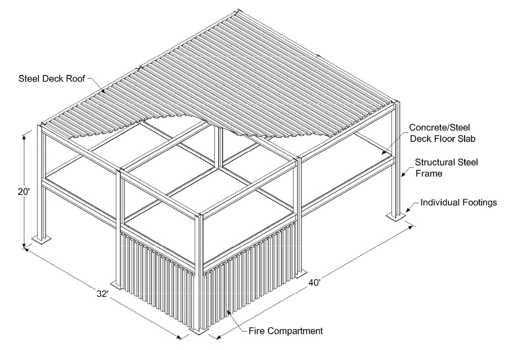
[This test] structure had a footprint of 32 [feet] × 40 [feet] and was 20 [feet] high (see Figure 4 [in the paper]). The frame was sized to represent a floor at mid-height of a 20-story office building and was fabricated of hot rolled structural steel sections fastened to columns with high-strength bolts. The floor slab at the second-floor level was subjected to a design live load of 80 lb/ft2 and consisted of normal weight concrete on a steel deck. During each of the tests, one 16 [-foot] × 20 [-foot] × 10 [-foot-high] bay of the test frame was exposed to fire and the structural steel and metal deck protected with spray-applied fire protection material, ½[-inch] thick. The assembly used a W12×22 beam framing into a W12×22 spandrel and W12×30 girder and was based upon UL Design No. N805 (UL, 2001), because of its similarity to the construction details being tested (see Figure 5 [in the paper]).
Both ASTM E119 fire exposures and ventilation controlled fires (freeburn, using wood pallets as the fuel) representing exposures expected in an office occupancy were used. Temperature measurements were recorded during and after the tests through the slab thickness, along the beam profile, on the columns in the test bay, and within the fire compartment. Vertical deflections were measured across the exposed portion of the floor slab and horizontal deflections were measured along the columns and spandrel beams of the test bay and in the fire compartment.
…The data from all three tests showed that the structural framing had equal or better fire resistance than a single beam in the ASTM E119 fire test protected in accordance with the restrained rating criteria. The guidelines in Appendix X3 of ASTM E119 for restrained beams were confirmed by these results.
Underwriters Laboratories, Inc. Fire Tests: 1983 – 1984
[These tests] investigated the similarities and differences during UL 263 (ASTM, E119) fire tests in the performance of restrained steel beams with different end conditions (UL, 1984). The end conditions investigated were:
- Beams restrained in the UL test frame in the traditional manner, by placing steel shims between the ends of the beams and the test frame; and
- Beams placed in the test frame using typical field bolted clip angle connections (see Figure 7 [in the paper]). Results of these fire tests, based on Table 1 in the UL test report, are summarized in Table 1 [in the paper]. In evaluating the test data from these fire tests and other tests, the UL report concluded the following:
There does not appear to be significant differences in the fire resistance performance of restrained beams that are shimmed against the test frame as compared to restrained beams that are bolted to clip angles in the manner described in this report. Thus, this test confirmed that beams with bolted connections should be considered as restrained beams.
Computer Modeling of the 1965 OSU/AISI Fire Tests: 1988
[Further modeling and analysis were performed considering] two components of end restraint in realistic steel-framed buildings:
- Rotational restraint, provided by simple bolted connections; and
- Axial restraint, due to column restraints, floor slabs, and adjoining construction.
Rotational Restraint
The minimum restraint condition used… was a connection generally considered as a pinned or simple shear connection by designers: a 3-bolt single plate framing connection. Figure 9 [in the paper] shows the results of the… analysis and the results of corresponding unrestrained and fully restrained beams. Figure 10 [in the paper] illustrates that the end moments due to the bolted end connections reduce mid-span moments and stresses at all stages of the fire test. More highly restraining connectors were not studied since a minimum-sized bolted end connection gave essentially restrained-based fire endurance.
Based on these results, [it was concluded] that a minimum amount of rotational restraint (no axial restraint considered) provided by simple shear connections produces a fire endurance that approximates that of the identical floor system assembly but with fully fixed, moment-resisting connections.
Axial Restraint
The… study for axial stiffness and its effect on fire endurance involved a W12×27 beam-slab assembly from the OSU tests, framed into a single W14×43 column. The column was assumed fixed one story above and one story below. Restraint due to both weak-axis and strong axis orientation of the column (the latter about ten times stiffer) were studied. The conclusion reached… was that axial restraint in the absence of rotational restraint does not increase fire endurance over that of minimal rotational restraint alone (see Figure 11 [in the paper]).
It should be noted that, although the component of restraint to the axial growth of beams provided by column stiffness can increase fire endurance of the floor or roof system, excessive restraint can cause buckling of beam flanges or damage to connections. Contrarily, very flexible columns theoretically could be subjected to significant horizontal deflections at the floor or roof level during heating or cooling. However, there are no known cases of actual uncontrolled fires in which any of these effects have impaired the performance or fire endurance of protected structural steel framing.
Combined Axial and Rotational Restraint
Results from analysis of combined axial and rotational restraint (weak-axis column orientation) are shown in Figure 12 [in the paper] and compared with unrestrained and fully restrained connections. Again, the conclusion drawn… was that, if minimal rotational restraint is provided by standard shear connections at the ends of the beam, restrained-based fire endurance is achieved even if there is little or no contribution from axial restraint. Steel framing in both interior and exterior bays will behave as restrained assemblies as long as the connectors are attached to columns or other members to develop some degree of rotational restraint, typically achieved with standard shear connections.
Other Findings
[This study also] validated the practical classification of restrained construction for structural steel in ASTM E119, Table X3.1. [It] also noted other practical factors that further support this conclusion, such as: continuity and redundancy; lower load levels during actual fires; and, composite action between steel and concrete. …
Recent Studies and Fire Tests
The authors have included the following remarks about several recent studies that reinforce the [points made in the paper].
Cardington Fire Tests: 1995 – 1996

View of Cardington Test Building during fire exposure.
[These] tests were conducted on an eight-story, steel-framed office building at the Cardington Laboratory of the Building Research Establishment in the United Kingdom (Newman, 1999) (see Figure 13 [in the paper]). …The structure was five bays long (148 [feet]) by 3 bays wide (69 [feet]) by 108 [feet-high], and beams in most of the tests were designed as simply-supported acting compositely with a concrete slab cast on metal deck. Columns were protected up to the underside of the floor slab and the beams, deck and floor slab in this unsprinklered building were unprotected.

Beam in Cardington Tests after reaching temperature in excess of 1,600°F.
Although the test program included one test on a restrained beam assembly on the seventh floor, it was noted that restraint as a variable in fire tests is largely unheard of in Europe. During this restrained assembly test, the maximum beam temperature reached was about 1,650°F and the maximum deflection was about 10 [inches] (see Figure 14 [in the paper]). Although distress was noted in the bottom flange of the beam and at the connections (during cooling), the floor assembly continued to support its applied load at the conclusion of the test (see Figure 15 [in the paper]).
Ioannides and Mehta: 1997
An analytical study on restrained/unrestrained fire ratings used the measured temperatures at various locations along the depth of the beam and slab to determine nominal flexural strength and capacity of a beam during the ASTM fire test (Ioannides and Mehta, 1997). The authors offered an analytical procedure, using an assumed time-temperature history for the particular assembly and beam rating coupled with the known properties of the steel at various elevated temperatures, to calculate the nominal flexural strength of the beam. They also provided methods to increase the nominal flexural strength (if needed) by accounting for the effects of rotational restraint (due to connections and slab reinforcement) and thrust restraint. Their study showed that, considering the combination of factors that occur in real buildings during real fires, steel beams, protected with spray-applied fire protection material thicknesses for restrained beams, can have sufficient load-carrying capacity without even counting on any restraint.
An Extreme Fire Event
Experience from intense, uncontrolled fires in unsprinklered structural steel high-rise buildings with spray-applied fire protection during the past few decades is limited. However, these few events have borne out the ability of steel and concrete floor systems to mobilize the surrounding structural elements and prevent collapse under the most intense of fire exposures. Perhaps the most dramatic example of steel’s fire endurance occurred in a high-rise fire in an East Coast city in 1991 – probably the most intense high-rise fire ever experienced in the United States (Klem, 1991). The fire was reported to have caused a complete burnout of eight upper stories over an 18-hour period, being halted at the 30th floor by sprinklers that were being retrofitted into the building from the top floor downward. Although there was considerable distress to steel floor assemblies (originally fire protected based upon a restrained rating classification), there were no reported floor collapses. Dexter and Lu (Dexter and Lu, 2000) later studied the effects of high temperatures and horizontal expansion/contraction and rotation of floor beams on the restraining columns.
Conclusions
- The unrestrained assembly fire resistance rating for structural steel beam floor and roof systems, based on ASTM E119 temperature criteria only, has no relevance to the behavior of these systems under uncontrolled fires in real buildings.
- The fire endurance of structural steel beam floor and roof construction under uncontrolled fire is enhanced by the interaction of the beams with the other structural elements and constructions that are integral with or surround the exposed assembly.
- All steel beam connections to other structural steel members exhibit both axial and rotational restraint.
- The least stiff connection typically used for steel framed construction (such as a three-bolt single plate connection) is adequate to develop restrained performance. Conclusions drawn from the fire research and computer modeling that have been performed by various agencies, including Underwriters Laboratories, Inc., support the conclusion that a restrained assembly classification and fire protection design is most appropriate for steel beam floor and roof assemblies, and verify the guidance contained in ASTM E119 …Appendix X3.
- The performance of structural steel beam and concrete floor systems exposed to uncontrolled fires observed during the research and analysis studies conducted during the past 25 years largely explains the excellent performance of these systems during severe fire exposures in unsprinklered, modern high-rise buildings.▪