A Multi-Use Path Curving to the Banks of the Charles River
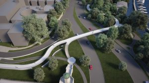
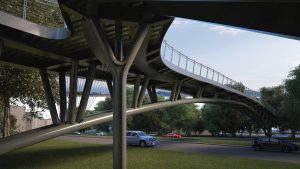
The Frances “Fanny” Appleton Pedestrian Bridge is a 750-foot long, multi-use path located on the banks of the Charles River in Boston, MA. This contemporary, curving, “ribbon-like” structure will be a signature bridge for Boston thanks to its geometrically challenging form. It will comfortably carry pedestrian crowds to and from the famous Boston Pops 4th of July fireworks concert. The pedestrian bridge is comprised of 550 continuous feet of elevated steel superstructure, including the 222-foot main span Vierendeel truss arch.
STV provided engineering design services to the WSC-Joint Venture of J.F. White Contracting Co., Skanska, and Consigli Construction Co., taking a preliminary design concept with unique architectural features to a final design concept. The firm’s work addressed fabrication, constructability, and pedestrian induced vibration performance.
Pedestrian Induced Vibrations
As one of the main connections to Boston’s landmark Charles River Esplanade, the bridge is expected to attract many visitors, including half a million people for the city’s annual 4th of July fireworks display. However, one of the structure’s principal features – its iconic slenderness – also makes it prone to vibrations. Controlling those vibrations in order to maintain pedestrian comfort was a critical challenge during the design phase.
The project team turned to SETRA (Service d’Etudes Techniques des Routes et Autoroutes), a technical guide referenced by AASHTO which provides a straightforward method to assess pedestrian induced vibrations. SETRA defines comfort levels based on structural accelerations. During design, multiple iterations were performed to achieve the “maximum” comfort range while minimizing the need for future supplemental measures, such as installing tuned mass dampers.
Unique Features
The bridge consists of more than 550 feet of continuous girders that curve in two directions, branching to stairs and a scenic overlook plaza. The structure’s steel fit-up required careful planning during the design phase, and construction over a busy city street necessitated a detailed erection plan. The team evaluated stresses in the members during both fabrication and erection.
Jointless Bridge
A major challenge for this unique bridge was the fabrication of the steel structure and its overall constructability. The preliminary design concept called for a structure with complex curves, with members meeting at tight acute angles, and welded connections at all member connections. The concept included a closed box section for the longitudinal girders in the approach spans and the main arch span. The team evaluated fabrication and erection tolerances and determined that box sections would be difficult to splice due to the squareness of the boxes and the curved nature of the beams and profile.
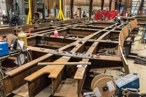
These challenges were compounded by the appropriate root gaps required for welding these connections, which would prove to be nearly impossible given the thermal movements of the bridge. The box girders were changed to a tub girder section of similar size. The tubs provided better access for making the connections, allowing a better fit-up of field splices. Because the webs and top flange are independent, internal diaphragms helped maintain the sectional dimensions. The welded splice was changed to a bolted splice, thereby adding flexibility to field drill along one side of the splice.
The bridge’s superstructure has expansion joints only at the abutments, 550 feet apart along the S shaped route. The live loading for the bridge was increased beyond AASHTO’s standard to 120 pounds per square foot to accommodate estimated crowd loading. The combination of the live load case and temperature effects on the steel expansion and concrete deck transmitted considerable loads to the abutments and the Wye piers, which were rigidly connected to the girders.
The mass of the structure was altered, to improve the overall vibrational response of the bridge, by removing the crown from the bridge deck, switching to a lightweight concrete deck, and changing the compressive strength of the concrete deck. Using a 120 pcf lightweight concrete deck, with foam filled stay-in-place forms, provided noticeable benefits: considerable increases in frequencies, minor improvement in acceleration, and substantial decrease in overall load. When combined with other improvements, such as changes to the steel framing, it shifted the structure out of the susceptible range.
Viernendeel Arch Span
The main arch span, which was comprised of diverging 18-inch diameter pipe arches and 14-inch HSS spandrel columns, was analyzed as a Vierendeel truss. The “top chord” of the truss is a composite concrete deck with steel tub girders. 3-D modeling was utilized to capture stresses of steel erection for the entire superstructure.
During the design phase, the splay angle (degrees from vertical) of the spandrel columns was adjusted to improve vibrational performance. The adjustment from 7 degrees to 15 degrees stiffened the truss span, thereby reducing acceleration and the bridge’s response to vertical and longitudinal loads. This adjustment gave a substantial improvement with no material cost.
“Ribbon-like” Appearance
The feature that creates the distinctive ribbon appearance is a steel fascia plate along the entire length of the concrete deck reveal. While acting as a concrete formwork during construction, the fascia is also architectural. The fascia plates were assigned as AESS and specified with tighter tolerances to achieve fit-up that will meet welding criteria and decrease the chances of localized waves. The fascia continues the ribbon appearance along the stairs; however, at that point, it becomes an integral side of the structural stair fascia box girder carrying the stair tread loadings. This member was redesigned to a thinner plate cross-section, making it easier for the fabricator to form. The majority of the plates are curved in at least two planes to meet the defined geometry.
The depth of the fascia box members for the stairs also changed from the original concept. The redesign allowed for easier detailing of connections and fabrication while increasing the stiffness of the lateral restraint that the stairs provide to the main span. Although increased horizontal stiffness was not required based on AASHTO or SETRA criteria, limiting the sway of the main span was a significant improvement. The increased stiffness of these members also reduced the deflection of the structure under service wind conditions. The fascia box girder changes to the stairs improved performance and required no additional material while maintaining the unique aesthetics of the bridge.
Wye Pier
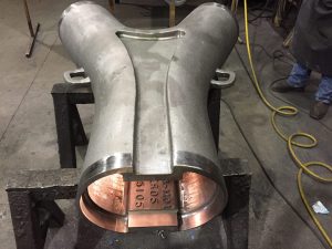
The architectural concept included steel Wye approach piers with an inset detail. This geometrically challenging form, which included a 4-inch radius within the arms, led the team to choose a steel casting to create the unique detailing. The base of the pier was formed as a built up section, and the casting was welded to the base. The top cap plates were provided with alignment studs for the tub girders to facilitate weld fit-up.
The piers’ welded connection to the superstructure created stresses within the piers due to temperature expansion and contraction of the girders. The foundation was modeled with an upper and lower range of estimated stiffness to make sure that the pier columns would perform as desired during temperature fluctuations. A separate check using rigid supports was also conducted to determine the effects of the ground freezing during the winter. Pier stiffness and flexibility were then adjusted as needed to meet the acceptable stress range for each pier. Adjustments included: stiffening with internal plates located at the base of the piers, increasing flexibility by revising local grading to increase pier heights, and setting the piers at each end of the structure on bearing pads to allow for rotation at the pile cap interface.
Another consideration for improving the vibration performance of the structure was revising its foundation stiffness. Original micro piles were changed to H-piles, resulting in a stiffer axis. Two pier foundations were changed to a three pile foundation with battered piles, altering the frequency of the west approach and lowering the overall response of the main span. Additional battered pile foundations were designed for the stairs which act as a strut, providing lateral restraint to the main span.
Conclusion
The Fanny Appleton Pedestrian Bridge uses architectural elements including a ribbon-like fascia running the extent of the bridge, unique Wye piers, and a slender arch span. STV worked closely with members of the design-build team to include cost-effective design modifications, to meet the architectural objectives, and improve constructability and the user experience. The bridge is currently under construction and is estimated to be completed in mid 2018.▪
Project Team
Owner: Massachusetts Department of Conservation and Recreation. Undertaken as part of the Longfellow Bridge Rehabilitation Project by Massachusetts Department of Transportation-Highway Division
Engineer of Record: STV, Boston, MA
General Contractor (Design-Build): WSC-Joint Venture of J.F. White Contracting Co., Skanska, and Consigli Construction Co., Boston, MA
Steel Fabricator: Newport Industrial Fabrication, Newport, ME with steel castings designed and supplied by Cast Connex Corporation, Toronto, Canada


