
Hudson Yards, located on the west side of Manhattan, is a 14-acre area experiencing a major expansion. This renewed interest in the parcel is spearheaded by Related/Oxford Properties, who acquired the overbuild rights of the yards of the Long Island Railroad. 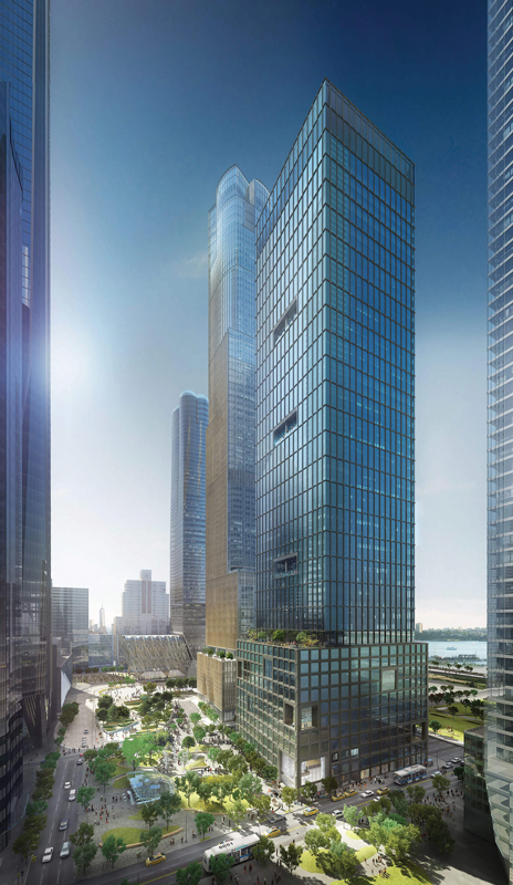 Considered the largest private real estate development to date in the United States, the Related/Oxford Properties Hudson Yards development will house about 19 million square feet of retail, commercial, residential, and mixed use spaces over the course of the next decade.
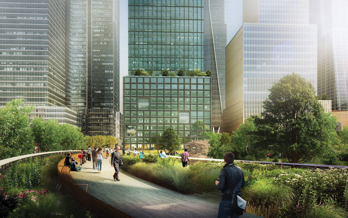
Working on new projects within urban areas is always a challenge considering the numerous existing constraints, including subway infrastructure, underground utilities, neighboring buildings, and difficult construction logistics. Although the 55 Hudson Yards site initially appeared to be a sparsely developed block, in reality, the site presents complex and difficult site conditions. It partially sits on top of the 34th Street-Hudson Yards subway station for the new No. 7 New York City subway and is occupied by a 6-story subway ventilation building. Another unique aspect of the 55 Hudson Yards structure was the use of a post-tensioned lightweight concrete flat slab floor system for a high rise commercial office building.
Project Evolution
The developer behind 55 Hudson Yards, Related/Oxford Properties, acquired the 55 Hudson Yards site from another major New York City (NYC) developer in early 2000.
While the initial developer pursued potential tenants, early designs for a steel diagrid building were proposed, and negotiations with the Metropolitan Transit Authority (MTA) took place to accommodate the infrastructure for the new No. 7 subway line. The negotiations resulted in an agreement to build the 34th Street-Hudson Yards subway station with portions directly below the office tower, including two major entrance escalators and a 6-story ventilation building. The agreement included a provision for the ventilation building and the below-grade subway station to have adequate capacity to support the proposed vertical and lateral loads imposed by the commercial office tower. Towards the end of 2007, construction of the station and adjoining ventilation building began and, by the fall of 2015, they were in service.
During the construction of the MTA infrastructure below and next to 55 Hudson Yards, the original developer sold the property and air rights to Related/Oxford Properties, which was constructing high-rise buildings adjacent to the 55 Hudson Yards site. Related/Oxford Properties immediately pursued the modification of the original tower design to meet their vision of a 51-story tower with 1.3 million square feet of gross area for commercial use. These changes resulted in architectural and structural modifications specific to the tenant base considered by the new developer. The redesign of the 55 Hudson Yards tower included two key structural considerations:
- Use of alternative structural materials, namely cast-in-place concrete, to meet the financial requirements of Related Properties. (This original concept was converted into lightweight concrete to reduce the loading upon the existing subway structure.)
- Redirecting the loads of the new tower to meet acceptable vertical and lateral load limits of the already built underground subway station and the 6-story subway ventilation building.
Project Description
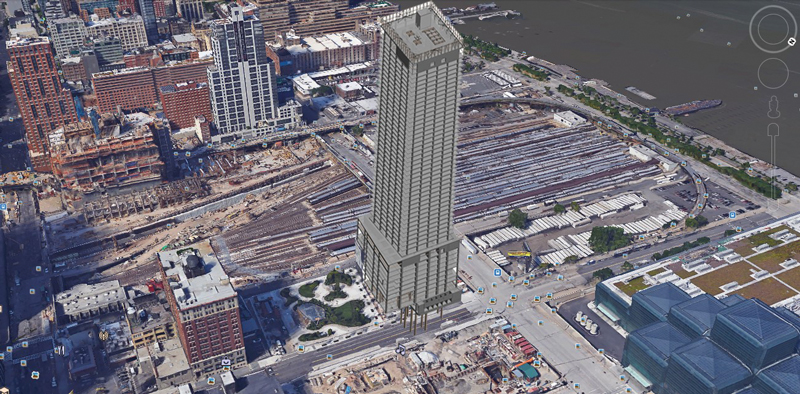
Figure 1. Existing site with structural rendering of the tower (background image obtained from Google Earth).
The 55 Hudson Yards project is located in the western half of the block limited by West 34th and West 33rd streets to the north and south, respectively. To the east, the project neighbors Hudson Park, where the main entrance of the 34th Street-Hudson Yards subway station is located (Figure 1). Furthermore, the new building neatly extends above and along the north side of the existing 6-story subway ventilation building in the southwest corner of the lot. The architects of the project are Kohn Pedersen Fox and Kevin Roche (John Dinkeloo and Associates). WSP USA Inc. provided integrated engineering services for structural and MEP systems.
The building is 51 stories high, divided into a 10-story podium and a 41-story tower, reaching 760 feet. The geometry of both the podium and the tower is approximately rectangular with column-free spans reaching almost 50 feet in the podium and more than 40 feet in the tower.
The combination of site-related constraints triggered by the MTA infrastructure and the limitations associated with the original design posed engineering challenges addressed by unique and highly innovative structural solutions.
Foundation System
The main objectives of the foundation system envisioned for 55 Hudson Yards were to address the large interaction with existing MTA underground facilities and to minimize the impact in terms of loads transmitted to those facilities.
The vertical load demands of the building were divided into three major components to provide adequate load-carrying capacity. Approximately 20% of the vertical load was transferred to the rock substrate by means of a reinforced concrete mat and footing foundations, about 40% was transferred using 10 reinforced concrete drilled caissons, ranging from 4.5 to 5.5 feet in diameter, and the remaining 40% was carried by the existing 6-story MTA ventilation building. The caissons were the primary support system for the concrete core and shear walls, carrying loads ranging from 10,000 to 33,000 kips.
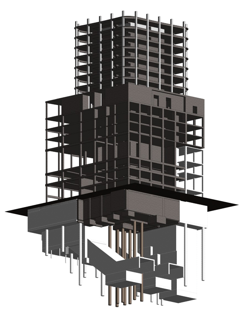
Figure 2. Foundation overview with detail of caissons between escalators.
Complicating the foundation design was the fact that the location of the caissons was limited to the area between the two previously constructed subway entrance escalators (Figure 2). The acceptable diameter and location for the caissons required the reinforced concrete core and shear walls to cantilever beyond the caissons, resulting in a 20-foot deep caisson cap. All caissons utilized 12,000-psi grout and were embedded into rock sockets below the escalator base to adequately transfer their loads into the rock below the escalator shafts (Figure 3). The length of rock sockets ranged from 35 feet to approximately 100 feet. To limit the caissons diameter and maximize their load-carrying capacity, No. 28 reinforcing bars with 75-ksi yielding strength were used. In exceptional cases, a solid steel section was provided in lieu of reinforcing bars.
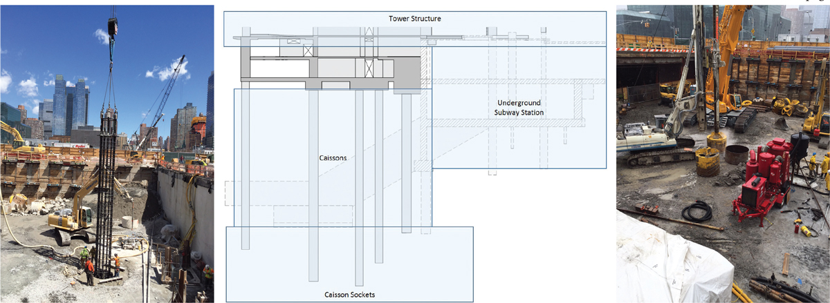
Figure 3. General layout of foundation system with details of caissons and caisson sockets.
Superstructure
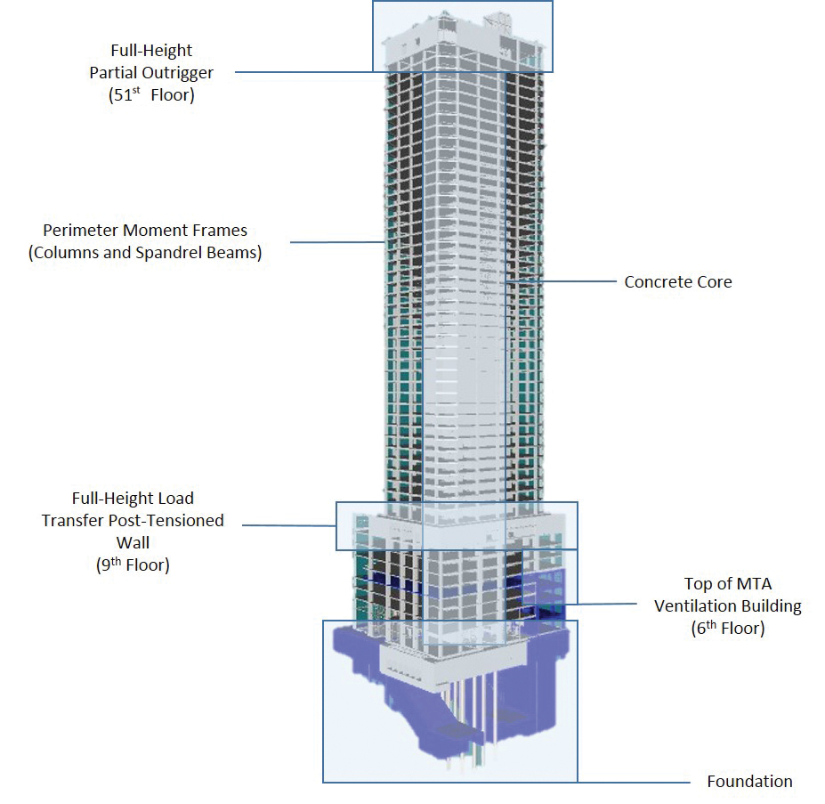
Figure 4. Structural overview. 3D view from Northwest.
The superstructure of the 55 Hudson Yards project is based on a central reinforced concrete shear wall core and exterior moment frames connecting perimeter columns with a spandrel beam around the slab edge of the tower. It is complemented by a partial outrigger and belt system at the top (Figure 4). The structural solution provided by WSP addressed three main design objectives:
- To follow the main architectural intent, which required long-span, column-free spaces.
- To minimize the structural weight and thus meet the load-carrying limitations of the existing 6-story MTA ventilation building and the underground subway station.
- To provide flexibility for future modification to the floor plans, specifically allowing for additional slab openings in selected locations.
The floor system was solved using a post-tensioned lightweight concrete flat slab. Floor slab thickness was primarily 9 inches in the tower and 10 inches in the podium, with 18-inch thick floors in areas of major load transfers. The compressive strength of concrete for slabs was increased during the construction phase from 7,000 psi, as required by structural analysis and design, to 8,500 psi to accommodate the required construction schedule by applying post-tensioning as early as possible. The increase in compressive strength allowed for the early strength required prior to the post tensioning operation.
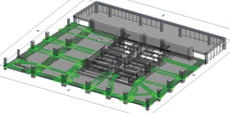
Figure 5. Example of 3D laser scan of as-built post-tensioning layout in a podium floor.
Despite the use of a post-tensioned system, which is somewhat unusual in the New York City market, this solution was more attractive financially than the original steel frame solution. It also was able to accommodate both the load limitations imposed by the existing subway structure and the floor plan flexibility for tenants. The post-tensioned concrete slabs utilized blended lightweight concrete, which went through an extensive pre-construction sample mix design study to assure its suitability, pumpability, and constructability under the project conditions. Three-dimensional laser scans were carried out at each floor level to determine the precise final location of post-tensioning strands (Figure 5) to address floor plan flexibility for future tenants. The post-tensioned slab utilized a banded system, thereby grouping the post-tensioning bands on either side of potential future slab openings.
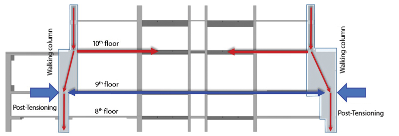
Figure 6. Load transfer mechanism using walking columns and post-tensioned slab.
The 9th floor is used as the primary mechanical floor and also serves as the interface between the podium and the tower floors. At this level, all the perimeter columns of the tower were transferred from a smaller tower footprint to the larger podium footprint. The transfer was accomplished with a walking column system where the 10th-floor slab carries in-plane compression loads, and the 9th-floor level carries in-plane tension loads. The 9th-floor tension forces were efficiently counteracted with undraped horizontal post tensioning (Figure 6).
Finally, to limit lateral deflections and accelerations due to wind events, a full-story height, partial outrigger and belt system connecting the central shear wall core with a number of perimeter columns on the north end of the tower was incorporated at the 51st floor of the tower.
Wind Tunnel Testing
Comprehensive and project-specific wind tunnel tests were performed at the boundary layer wind tunnel lab at RWDI Consulting Engineers to determine direct wind pressures and wind-induced building accelerations. The industry-recommended comfort level for human occupancy in terms of acceleration due to wind for office buildings was achieved.
Structural Modeling and Innovation in Construction Sequencing
The structural modeling of 55 Hudson Yards included full three-dimensional sequential construction analysis with consideration to time-dependent changes in material properties and loading demands. This analysis was necessary to assure the short-term and long-term loading on all existing subway foundation elements was kept within acceptable limits.
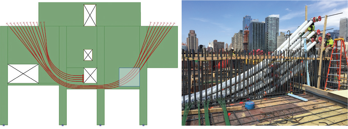
Figure 7. Post-tensioning scheme and detail of construction of transfer wall.
Two unique methods of load redirection were used to remove excessive loads from existing foundation elements or superstructure components of the subway structure. The first method was the innovative use of construction sequencing devised to prevent overstressing of critical elements of the MTA structure. A multi-strand, grouted post-tensioned system was used as a transfer wall to bridge loads away from the MTA structure (Figure 7).
The second method employed temporary load-path bridging to avoid specific locations with limited support capacity. After the appropriate amount of load had bypassed a specific location, the supporting structure was engaged using steel plate shims which then created a new continuous load path through the initially bypassed support points.
Material and Construction Innovations
High-performance structural materials were used in 55 Hudson Yards to provide adequate stiffness, strength, and resilience. For columns and shear walls, a concrete compressive strength of 12,000 psi was used in all podium floors, which gradually reduced to 7,000 psi at the 51st floor.
Considering the load-carrying capacity limitation of the existing 6-story MTA ventilation building, it was crucial to reduce the weight of the structure without jeopardizing its structural integrity. With the use of 9-inch thick blended lightweight concrete slabs, the appropriate building weight was attained. The concrete supplier was able to develop, test, and successfully produce a mix design for a pumpable, lightweight concrete with a specified compressive strength of 8,500 psi at 56 days. The blended lightweight concrete was produced using both traditional lightweight and smaller diameter coarse aggregates and had a volumetric weight of approximately 130 pcf instead of the 150 pcf associated with normal weight concrete.
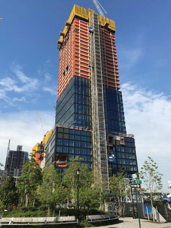
Figure 8. 55 Hudson Yards tower under construction as of May 2017.
In conclusion, this project demonstrates unique and innovative solutions to overcome existing site constraints. These constraints are becoming more prevalent in cities as developers seek out previously undeveloped land within urban centers. Also, the use of post tensioning, coupled with light weight concrete, a rarity on commercial high rises, is proven to be an economical alternative to structural steel framing. See Figure 8 for an overall view of the project under construction as of May 2017.▪
Additional Credits
Fatih Yalniz, P.E., is Structural Analysis Manager and Vice President of Building Structures at WSP USA.
Mehrfam Pour-Manouchehri, P.E., is Senior Associate of Building Structures at WSP USA.
Gerardo Aguilar, Ph.D., is Technical Manager of Building Structures at WSP USA.
Angel Eng, P.E., is Project Manager of Building Structures at WSP USA.