
Once in a while, every engineer encounters a project that presents new opportunities for innovation and advancement. Almost seven years ago, it was a small chiller plant that tempted me to dabble with a new software called Revit, which was slowly making its way into our industry. Today, Building Information Modeling (BIM) is a household name in the A/E community where interoperability between documentation, analysis, design, and fabrication models can be achieved. But how close are we really from taking the architectural massing model from concept to fabrication in an efficient manner? I recently had the opportunity to address that question in the design of a 36-foot tall monumental exposed steel tower structure. Once the team decided to step away from traditional design methods and embraced the new technologies, the answers I found were surprising.
Working in a 3D Environment
The basic concept is simple: Instead of independently working toward a 2D set of drawings, working models are developed simultaneously and teams can provide information to each other via software interoperability. One of the immediate efficiencies of this model evolution is that each of the stakeholders involved is only responsible for modeling their respective area of expertise and can still use the software of their choice. Eventually, traditional 2D sheets are created, but they don’t dictate the order in which work is done. They are a byproduct of the model.
This is part of that paradigm shift we have been hearing about for some time. BIM is not the latest drafting tool; it’s a collaborative, data-rich design and visualization tool. It requires the model author to challenge the way software is being used, beyond its spatial benefits into a holistic understanding of the project and process. He or she must understand the sequencing, Level of Development (LOD) needed and modeling responsibilities required by each party. To achieve this shift, a collaborative effort is required early in the project: clearly define modeling responsibilities, establish a consistent sequence so everyone develops the same areas at the same time, and bring all those different file formats together.
Identifying a project team as soon as possible helps establish those responsibilities. Some of those relationships need to be established contractually. For the tower structure, the steel fabricator was brought on board during the design phase while the structural model was being developed. Since most of the steel connections were exposed and required architectural input, the structural engineer was responsible for their design. But it was the steel fabricator that modeled them. Identifying that relationship early allowed the design team to save time by not drawing lines in 2D details to communicate design intent. Clearly defining roles and responsibilities and setting up a protocol for file sharing prevented any duplication of work, which was a key objective for this project. Similar agreements were made with the architectural partners regarding the non-primary structural elements.
Interoperability and Modeling Practices
When it comes to interoperability in the structural world, we have focused mainly on links between documentation and analysis models. As engineers, we want reliable and trustworthy tools, and tend to discredit new software that is not perfect. However, is our waiting for software developers to perfect the link between documentation and analysis models preventing us from moving forward on other BIM-related progress?
The design team for the tower structure understood each program’s limitations and was able to get a number of software with very different functions to share information. The architects used Rhino first and SketchUp later for visualization. The engineering team relied on Revit and RISA 3D for coordination, analysis and design. The steel fabricator worked in SolidWorks. All the files were linked through either direct bi-directional links or file exchange formats (IFC, DWF). Some models only shared spatial information, while others provided physical and analytical information.
Rhino and Revit
There is no direct link between these two platforms. The architectural conceptual model was exported to a DWF format that could be linked into Revit, where the structural engineer modeled the primary structure. This structural file was exported so it could be used in both Rhino and SketchUp as a background. The models were adjusted and re-exported with ease several times during numerous design iterations.
Revit and RISA 3D
Once the structure was defined, the analytical Revit model was adjusted to disregard miscellaneous steel, and was exported to RISA 3D using the bi-directional link available. As the architectural concept changed, several roundtrips took place to update the structure geometry in the analysis software. As that occurred, iterations of structural analysis and design were performed in RISA 3D and the most current member sizes were automatically pushed to Revit.
Revit and SolidWorks
As the structural design was being finalized, the Revit file was shared with the steel detailer through an IFC export. The geometry and member sizes were validated as the SolidWorks model was started. The fabricator exported that model to IFC, DWF, IGS, and DWG formats for the structural team to link into Revit once the preliminary connections were created. Iterations in connection design occurred with model revisions and electronic markup tools.
Revit became a centralized location that was updated to reflect the latest architectural changes, which could then be shared with the structural design team and fabricator. In essence, the architectural massing model evolved into the steel fabrication model. At that point, the project became a communication-driven effort with multiple iterations of model sharing, virtual walkthroughs, and PDF markups of model screenshots.
As important as these modeling and sequencing techniques are to drive efficiencies, communication was key to success. Setting expectations, verifying roles and responsibilities various times along the way, and sharing progress were paramount. We have all heard the old carpenter saying: “measure twice, cut once.” Well, BIM is no different: “talk twice, model once.”
Benefits
The most important consideration of any innovative effort is to prove its validity and justify the risks taken with clear benefits. As the team embarked on this venture, the hope was to achieve design efficiencies by challenging traditional workflows. But a number of unexpected benefits emerged.
The benefits of interoperability were exploited by the ability to effortlessly create construction documents. After the models were complete, plans and elevations were created, sections were cut, and sheets were built in Revit. Since all the physical information was available, 80 percent of the annotations required to finalize the drawings were smart tags that required no manual input. The rest were notes and weld symbols added manually. No lines were drawn, everything was modeled. Figure 1 shows the evolution of the model at a specific connection.
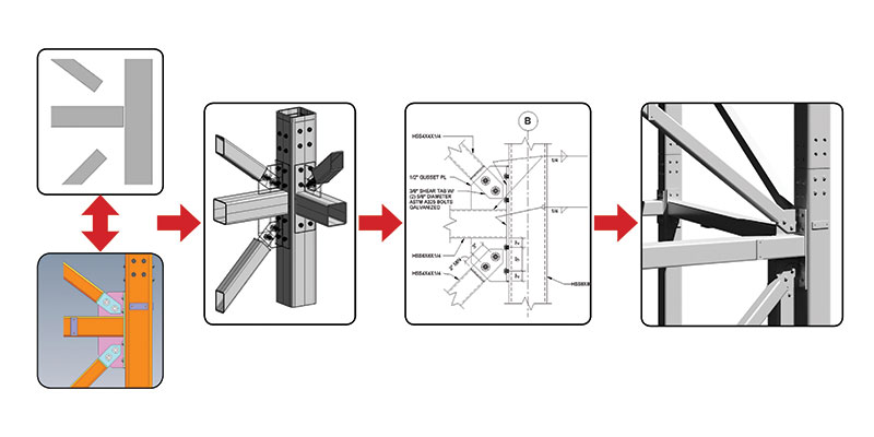
Interoperability between Revit and SolidWorks allows for the creation of complete construction documents without drawing any lines.
Constant information exchange allowed the design team to avoid duplication of elements, which yielded design efficiencies and cost savings. Design time was reduced considerably because no efforts were reproduced: the architects did not have to model a structure during their conceptual design phase, the engineer did not have to model or draw connections, and the fabricator did not have to start a model from scratch.
The project was designed in electronic format, making it entirely paperless. Working in models instead of sheets required no plots or prints. Submittals were also reviewed and approved electronically, including the steel shop drawings that were generated from the SolidWorks file.
The open exchange of information resulted in a better coordinated project. Coordination is sometimes measured in the number of clashes reported during or after design, but in this case they were nonexistent.
Having accounted for all parts of the structure in the different models, accurate quantity take-offs and bills of materials were automatically created. In addition to providing the total tonnage of steel, the models yielded miscellaneous steel quantities, number and sizes of gusset plates, and number of bolts.
Conclusion
In these days of economic uncertainty, it often seems like there is little time to focus on innovation. However, now more than ever, it’s important to exercise continuous improvement and find better and more efficient ways to do our work. There are many BIM tools available from different software developers, but the existence of these tools alone is not enough. It is our duty as engineers to find ways to utilize them in inventive ways to push our firms and our industry forward. What a great time to discover innovative ways to design our structures. What a great time to experiment with new technology and influence its development. What a great time to be an engineer.▪