
Rebuilding with Site Constraints
Upon opening its doors in December of 2015, Dallas Fire Station #27 was recognized as special in a number of ways: 1) It is one of only four currently operational multi-story fire station facilities for the Dallas Fire-Rescue Department (DFRD), and the first one built in the last 50 years; 2) Very few fire stations are composed of a concrete frame superstructure; 3) Only a handful of fire stations are LEED registered (Fire Station #27 is currently pursuing Gold certification); 4) No other Dallas fire station has an underground parking garage; and 5) The multiple points of entry required for the apparatus bay is unique, especially when it located at a very busy urban intersection. The structural challenges presented by these last two features are addressed in the following discussion. But first, here is a brief history of how these site constraints developed.
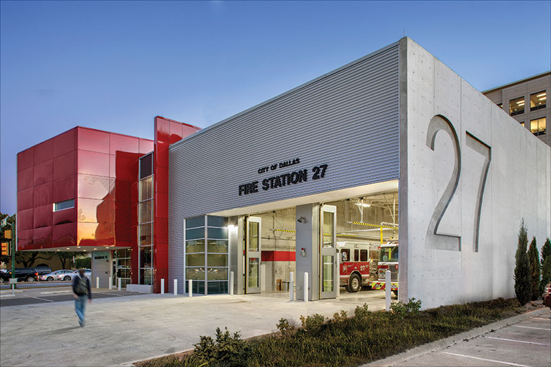
Courtesy of Thomas McConnell, Perkins + Will
Considering the fifty-seven fire stations that the DFRD manages for the city of Dallas, Texas, it can be difficult for an individual station to achieve distinction. With such a long history of service covering a large metropolitan area, the DFRD has utilized dozens of facilities to house their dedicated personnel during more than 140 years of operation. Despite the simplicity, utility, and efficiency these facilities are tailored to meet, an exceptional one pays special homage to the fine men and women who vigilantly maintain the protection of the community as their primary focus.
The 23,000 square-foot building did not aim to accomplish each of the feats indicated above purely for the sake of differentiating itself from other facilities. The driving factors for some of these accomplishments were a result of necessity. The original station, which opened in 1948, was a single-story structure of a little less than 5,000 square feet which served the fringes of the growing city of Dallas. However, as the surrounding community began to urbanize, and the quantity of single family and multi-family residences and supporting commercial development increased exponentially, it became apparent the facility needed to be modernized.
The existing lot encompassed just over 18,500 square feet. To accommodate new quarters, an apparatus bay, parking allotment for firefighters and visitors, and ingress/egress that could meet the minimum requirements for apparatus functionality and access to the street, the primary challenge was already evident.
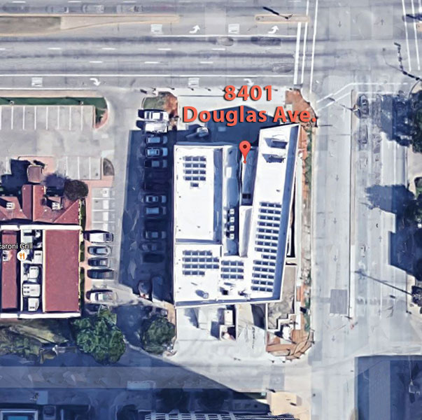
The lot was tucked into the east end of Preston Square, aligned with the southwest corner of the intersection of the Northwest Highway thoroughfare and Douglas Avenue, making the difficult task even more daunting. To the south of the lot (beyond the typical easement) was Berkshire Lane, a public street. Directly to the west of the property was an operating restaurant that, despite accommodating the City as much as possible, required functioning parking spaces and vehicle access to remain operational throughout the duration of demolition and construction activities.
The design scheme to accommodate all of the site constraints required building vertically while maintaining grade level access to the apparatus bay to preserve efficient response times. This meant that building a basement level to move the required parking below grade was the most feasible solution. Within this solution, it was deduced that the access ramp would need to be a single entrance/exit ramp so as not to conflict with the apparatus operation, and so as not to limit the quantity of parking spaces available to the eighteen firefighters Station #27 was intended to house.
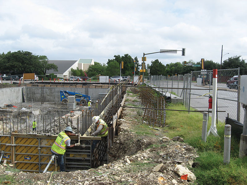
A more than 14-foot deep excavation was required to set the basement level and install the footings supporting the concrete frame and walls. The extent of the 7,500 square foot basement was squeezed into the northeast corner of the site, with basement walls located four feet from the east property line and 13 feet from the north property line. This was to allow the apparatus bay to align on the west side of the building, the foundation of which was to bear on compacted subgrade backfilled against the west basement wall. This facilitated access for apparatus to enter the facility and turn out onto the busy intersection that handles more than 29,000 vehicles per day. Due to such a high traffic count and landlocked site, the excavation required the installation of a temporary earth retention system along the north and east sides of the basement. This allowed for continued use of adjacent roads without restriction throughout the construction.
The solution implemented by Ancortex Inc. and AP Engineering Consultant, Inc., was a cantilevered soldier pile retention system with timber lagging, constructed of W6x25 piles embedded six feet into the limestone stratum and encased in a ten-inch diameter grout filled bore spaced at 4 feet on-center. The footing for the east basement wall extended 12 inches beyond the exterior face of the wall but, due to the eccentric loading of the upper-level structure in some locations, the footing extended a minimum of 24 inches from the exterior face of the wall for about 50 feet. As a result, a two-sided forming system by Doka USA was utilized for the basement wall construction, with traditional diagonal strut bracing onto the basement slab to brace for loads imparted by concrete installation and backfill placement between the lagging and the basement wall. This also proved to be a difficult task, as utility easements ran along the east edge of the site and a workable cavity space was required to apply waterproofing. A low strength flowable fill (gravel mixture) was used for backfill because of the lack of space for compaction.
The underlying soils at this site consisted of a stiff clay for the upper four feet, weathered tan limestone for the next six feet, and a hard gray limestone layer occurring approximately 10 feet below grade. This soil/rock profile was a positive, as it allowed the use of shallow footings bearing at the basement level. However, this required excavation of between four to nine feet of limestone materials which necessitated the use of heavy rock excavating equipment.
Furthermore, a few (granted simpler) challenges were presented because the apparatus bay slab was bearing on compacted subgrade. The west wall of the apparatus bay was flushed up against the property line adjacent to the restaurant. To maintain similar foundation bearing for the structural cast-in-place concrete wall along this side, drilled concrete piers bearing on the limestone were installed offset from the wall so as to have clearance away from the plat restriction. Eccentrically loaded pilasters were designed with the grade beam placement so that a cold joint could be placed for the wall construction.
The width of the apparatus bay extended a few feet over the western-most basement wall, which was constrained due to the two-way access to the parking level. That basement wall required the design of the hydrostatic forces behind the wall (considering a drained condition as perforated drain pipe ran along the bottom of the wall) with an additional surcharge load of 250 psf for the apparatus bay.
The north end of the parking garage roof structure extended beyond the footprint of the building above, which presented another challenge. The concrete joist floor structure for the 1st level required a 4-inch depression at the building transition to exterior parking and driveway to accommodate a paver system, and needed to be sloped at 2% grade away from the building. The depth of the structural system was limited to maintain minimum overhead clearance in the garage for vehicles. This resulted in the use of wider joists and narrower pans. To mitigate potential overhead conflicts, building utilities such as fire sprinkler lines were run between the narrow pan joists. Trunk lines were sleeved or cored through the joists. As a result of a portion of the 50,000-pound apparatus being able to turn out over the structured garage roof, the joists and girders in the end bay required that the design apply 2/3 of the load applied on an individual axle and additional analyses involving the moving wheel loads.
In summary, Fire Station #27 achieved its primary goal: to provide an efficient and modern facility for the brave firefighters who call it home, while also standing out as a monumental structure that honors all firefighters who protect the city of Dallas.▪
Project Team
Owner: City of Dallas, Texas
Structural Engineer of Record: JQ Engineering, LLP, Dallas, Texas
Architect of Record: Perkins+Will, Dallas, Texas
General Contractor: Bartlett Cocke General Contractors
References
Historical fire station 27 data, and DFRD statistics provided by Dallas Fire-Rescue Department.
Map provided by Google Maps
Traffic count, North Central Texas Council of Governments.