
Membrane roof systems installed on steel roof decks traditionally result in a uniform transfer of wind (uplift) loads from the roof membrane to the steel roof deck and underlying supporting structure (e.g., steel joists). For example, in a built-up membrane roof system – which has been used commonly in the U.S. roofing industry for more than 125 years – the built-up membrane is continuously adhered to rigid board insulation. The rigid board insulation, which is used to span the steel deck’s flutes, is mechanically attached to the steel roof deck in a closely-spaced pattern (e.g., 1 fastener per every 3 square feet), resulting in a near uniform uplift load path. Polymer-modified bitumen roof systems and adhered single-ply membrane roof systems are installed in similar configurations and result in a similar uniform uplift load path.
In the 1960s, single-ply membrane roof systems were first introduced into the U.S. roofing market. By the late 1970s, the seam-fastened, mechanically attached method of installation was first introduced. With this installation method, the single-ply membrane sheet is mechanically attached along its outer edges into the roof deck, which results in a larger tributary uplift load per fastener and placement of fasteners in linear, non-uniform loading configurations of the roof deck and underlying supporting structure. When first introduced, membrane sheet widths in seam-fastened single-ply membrane roof systems typically were five feet wide, resulting in rows of mechanical fasteners spaced at five feet on-center. Since the early 2000s, single-ply membrane sheet widths have become wider, with 10-foot-wide sheets now commonplace – resulting in rows of mechanical fasteners spaced at 10 feet on-center.
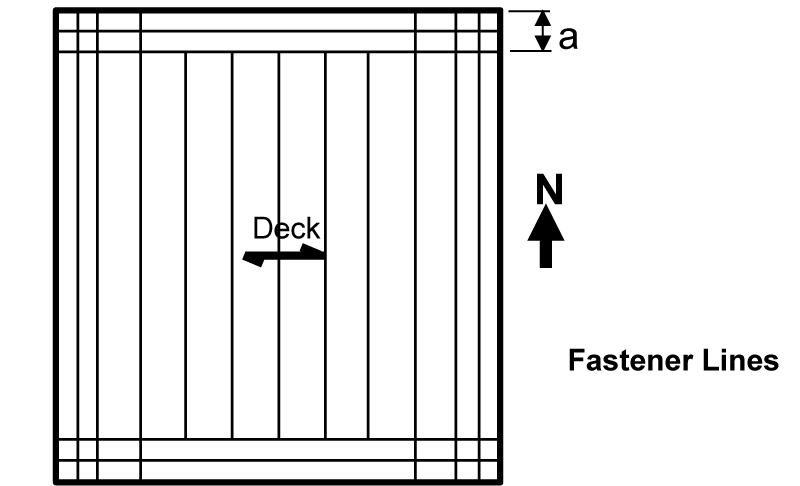
Figure 1. Typical membrane layout by roofers.
Currently, single-ply membrane roof systems have clearly overtaken conventional built-up and polymer-modified bitumen membrane systems in market share. The seam-fastened, mechanically-attached method of installation also has overtaken traditionally adhered methods of application. The National Roofing Contractors Association (NRCA) annual market survey shows seam-fastened, mechanically attached single-ply membrane roof systems make up the majority of all membrane roof systems currently installed.
With the present emphasis on wind resistance in design, a closer look at how seam-fastened mechanically attached single-ply membrane roof systems interact with steel roof deck and joist construction is in order.
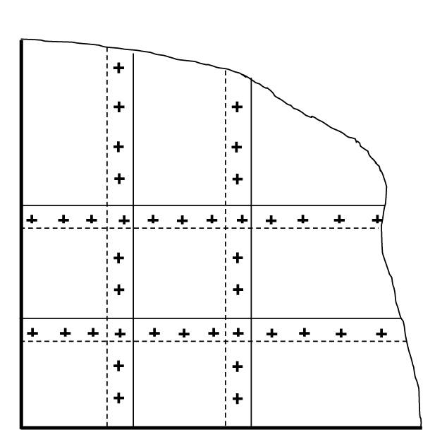
Figure 2. Typical fastener layout at corner zones.
A common method of single-ply membrane sheet layout is shown in Figure 1. A common placement of mechanical fasteners is shown in Figure 2. These concentrated line loads can severely overstress the steel deck and may also cause the steel joist below the deck to be overstressed under uplift loading. The behavior of such fastening systems, when the roof system is subjected to uplift loadings, is shown in Figure 3. The current trend in securement is for the membrane installer to mechanically fasten the membrane to the deck only along the edge of the sheet rolls to speed up the roof installation, thereby lowering installation costs. Unfortunately, the Structural Engineer of Record, and the steel deck and joist suppliers, are usually unaware of the concentrated load pattern of the roof membrane attachment. In fact, the architect of record may not be aware of the ramifications of such attachments. The Architectural roofing specifications may simply state that the roof membrane shall be installed per manufacturers recommendations. The roofing installers foreman is the one who generally decides on the exact layout of the membrane sheets on the roof. That decision is made based on what layout can be installed in the fastest and least expensive manner. Roofing suppliers and FM Global recommend the fastener line loads not be installed parallel to the deck ribs, but rather perpendicular to the deck flutes. Placing the lines of attachment parallel to the deck ribs will only load a one-foot width of the steel deck. This recommendation helps but may not eliminate potential severe overstress of the deck.
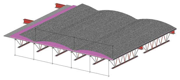
Figure 3. Line attached membrane under uplift. Courtesy of the Steel Deck Institute.
Currently, the Steel Deck Institute’s (SDI) position paper, Attachment of Roofing Membranes to Steel Deck, states: “SDI does not recommend the use of roofing membranes attached to the steel deck using line patterns with large spacing unless a structural engineer has reviewed the adequacy of the steel deck and the structural supports to resist the wind uplift loads transmitted along the lines of attachment. Those lines of attachment shall only be perpendicular to the flutes of the deck.”
Deck Strength Example
To illustrate the potential effect of the attachment pattern, determine the deck strength for the following conditions illustrated by Figures 1 and 2. Use Load and Resistance Factor Design (LRFD) Load Combinations and American Society of Civil Engineers’ ASCE 7-1. Thus, the controlling ASCE Load Combination is 0.9D + 1.0W. (Wind calculations are not shown for brevity.)
Given: A roof system located in Kansas City, MO. Category II Building. Exposure C per ASCE 26.7.3. The building is an Enclosed Building with a flat roof (¼-inch per foot). The building is 100 feet by 100 feet in plan and has an eave height equal to 30 feet.
The metal deck is 1.5-inch 22-gage, wide rib (WR) deck on joists 6 feet on-center. Fy = 33 ksi. The roof dead load on the metal deck = 5 psf. The membrane is 10 feet wide in the interior zones and 5 feet wide in the perimeter zones.
From the SDI Roof Deck Design Manual (RDDM), φMn (negative moment capacity) = 5.358 kip-inches, and φMp (positive moment capacity) = 5.088 kip-inches.
Interior Zone (Field of Roof)
Uplift line loads are determined using Component and Cladding ASCE Requirements (ASCE Chapter 30).
The fasteners are placed perpendicular to the deck span and are spaced 1-foot on-center. Therefore, the membrane area is 10 square feet (1-foot x 10-foot-wide sheet). The uplift pressure is 33.3 psf.
Assume that, at some location in the field of the roof, the fastener line will be located at the center of a deck end span. From a structural analysis of a three span deck, the maximum moment occurs in the end span (positive moment); Mr = 4.85 kip-inches. For a uniformly loaded deck, the maximum moment occurs over the two supports (negative moment); Mr = 1.24 kip-inches.
East-West Perimeters (Attachments Perpendicular to Deck Span)
The first line load is 5 feet from the building edge and the second is 10 feet from the edge. The third is 20 feet from the edge.
First Line Load: The membrane area for the first line load = (5 foot) = 5.0 square feet.
Second Line Load: The membrane area for the second line load = (2.5 feet + 5 feet)(1.0 feet) = 7.5 square feet.
Third Line Load: The membrane area for the third line load = (5 feet + 5 feet)(1.0 feet) = 10.0 square feet. The uplift pressure is 55.8 psf for the first 10 feet from the building edge and 33.3 psf for the remainder of the three span deck.
The maximum moment is 4.32 kip-in and occurs in the second span as a positive moment. For a uniformly loaded deck, the maximum moment is 2.31 kip-inches (negative) and is located over the first support from the building edge.
North-South Perimeters (Attachments Parallel to Deck Span)
Note: Fasteners running parallel to the deck flutes is a severe condition and not recommended. If used, the following loading conditions occur.
Line Load: Parallel to Deck Flutes
The uplift pressure is 55.8 psf.
The membrane area for the line load = (5 feet) = 5 square foot.
Line Load on 1.0 foot of deck width = (5.0 feet)(55.8 psf)- 4.5 plf = 275 pounds per foot
Positive moment = Mw = (0.08)wL2 = (0.08)(0.275 kips per foot)(6.0 foot)2 = 0.79 kip-feet = 9.50 kip-inches.
Negative moment: Mw = (0.10)wL2 = (0.10)(.275 kips per foot)(6.0 foot)2 = 0.99 kip-feet = 11.9 kip-inches.
For a uniformly loaded deck, the maximum negative moment is 2.22 kip-inches.
Corner Condition Zone
The uplift pressure is 84.0 psf for the first 10 feet from the building edge, and 55.8 for the remainder of the three span deck.
Line load on 1.0 foot of deck width = [(5 feet)(84 psf)]/2-4.5 plf = 206 pounds per foot for first 10 feet. The division by 2 is to account for load distribution between fastener lines. Then (5 feet)(55.8 psf)-4.5 plf = 275 pounds per foot beyond.
Based on a continuous beam analysis, the maximum negative moment equals 11.55 kip-inches and occurs over the second interior support from the corner. The maximum positive moment occurs within the third span and equals 9.64 kip-inches. For a uniform load, the maximum negative moment equals 3.48 kip-inches and occurs over the first interior support. The maximum positive moment occurs in the first span and equals 2.73 kip-inches. See Table for a summary of the conditions.
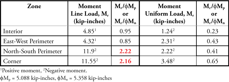
Summary table of required deck strength to actual deck strength.
Conclusions
North-South Perimeters and Corner Zone failures occurred. It is interesting to note that, with the amounts of overload shown in these calculations, there are not more reported deck and joist failures. There may be a number of reasons for fewer reported failures. For example:
- The design uplift anchorage of the deck to the joists, while increased for mechanical attachment as compared to adhered membranes, does not exceed the factors of safety in the design of the deck attachment fasteners.
- The majority of roofs have not seen roof uplift loads of those predicted by ASCE 7 because the U.S. has not been impacted by a major hurricane in over 10 years.
- The decks may have higher yield strengths than those used in the design example. The SDI RDDM tabulates roof deck capacity based on a lower bound yield stress of 33 ksi. Many manufacturers provide decks with yield stresses of 40, 50, or 80 ksi (limited to a 60 ksi design stress by the AISI S100 Standard). A design stress of 60 ksi versus 33 ksi will increase the deck flexural strength by about 70%.
Application When Re-Roofing
An important point to note is that, per NRCA, approximately two-thirds of the roofing installed every year is re-roofing of existing buildings. Buildings that are 20 to 30 years old are unlikely to have higher yield strength steel deck. Therefore, caution is required when evaluating roof deck when re-roofing.
Higher Wind Regions
The analysis described above was performed on a building located within the basic wind velocity zone of 115 mph per ASCE 7-10. Particular attention must be paid to the design of the deck for regions where the wind velocity is higher. At higher design wind speeds, a deck which is adequate to support an adhered membrane roof with uniform uplift deck loading may not be structurally adequate to support widely spaced line loads from a mechanically attached membrane roof.
FM Global Requirements
Often times, FM Approval Standard 4470, Single-Ply, Polymer-Modified Bitumen Sheet, Built-Up Roof (BUR) and Liquid Applied Roof Assemblies for use in Class 1 and Noncombustible Roof Deck Construction, is required for roof systems. These requirements are more stringent with respect to deck spans and thicknesses because the FM Standard uses a Factor of Safety of 2 (see clarification below for updated information), whereas the AISI S100 Standard mandates an ASD Factor of Safety of 1.67 for flexure. These requirements can be found on their RoofNav website. Go to www.roofnav.com and select Reference Materials followed by Approval Standards. The FM Standard provides wind ratings based on fastener row spacing, deck spans, deck thicknesses, and deck yield strengths.
For the above example, for a 33 ksi, 1.5-inch. WR deck spanning 6 feet, a 20-gage deck is required to obtain a 60 rating (30 psf ASD).
Clarification
This article refers to FM Approval Standard 4470 regarding steel decks and a Factor of Safety of 2. In fact, the FM Global requirements for steel deck is covered in FM Approval Standard 4451, Approval Standard for Profiled Steel Panels for Use as Decking in Class 1 Insulated Roof Construction and FM Global Property Loss Prevention Data Sheet 1-29. FM Approval Standard 4451, Section 4.3.1.6 states, “Stresses induced to steel roof decking shall be determined by rational analysis using Allowable Strength Design (ASD) principles and shall not exceed the allowable stresses per the latest edition of the North American Specification for the Design of Cold-Formed Steel Structural Members, AISI S100-2007.” FM Global Property Loss Prevention Data Sheet 1-29, Section 2.2.3.2 includes tables that are based on ASD principles and the allowable stresses per AISI S100-2012. This section also allows for “a performance-based approach” with the required assumption (Subsection C), “Assume maximum allowable stresses are determined using allowable strength design (ASD) in accordance with AISI S100-2012, or comparable standard outside the United States.” Therefore, the FM Global requirements are no more stringent than AISI S100 for steel deck spans and thicknesses.
This confusion may have been the result of interpretation of the definition of Service Wind Load within FM Approval Standard 4470 which states, “The uplift load resulting from a windstorm that a roof assembly must resist. The service load is equal to one-half of the rated load in psf (kPa).” As part of the FM Approval process covered by this Standard, Simulated Wind Uplift Pressure Testing is performed on roof assemblies. The rated load achieved by a particular roof assembly in uplift pressure testing is equivalent to two times the uplift pressure from a windstorm the roof assembly is required to resist. Therefore, the factor of safety of 2 applies only to the performance of a roof assembly during uplift pressure testing. It does not apply to deck span calculations.
Anthony Longabard
Staff Engineering Specialist
FM Global
Recommendations
Design recommendations for single-ply roofing when concentrated line securements are used to connect the membrane to steel roof deck instead of uniformly distributed securements include:
- When FM Global requirements are to be followed, maximum deck spans, deck thicknesses, and deck yield strengths as required by FM Global must be used.
a) Based on the maximum concentrated line loads determined from FM Global, specify the required joist net uplift.
b) Coordinate your design requirements with the general contractor and the architect.
2. When FM Global requirements are not required:
a) Determine the uniform net uplift forces based on the building code in force.
b) Using the spacing between the lines of fasteners for the membrane, perform a structural analysis of the deck as a 3-span beam, placing the first concentrated load at the mid-span of the first deck span. The subsequent loads are placed according to their spacing. This analysis will produce a moment diagram that is close to the maximum that would be achieved from an influence line analysis.
c) From this analysis, specify a deck that has a flexural capacity that exceeds the maximum positive and negative design moments.
d) If no deck is found that will work, change the spacing of the supports (joists) or alter the spacing of membrane fastening. Changing the spacing of the membrane fastening is something that requires coordination with the entire roofing team (specifier, manufacturer, and installer).
e) Determine the net uplift requirement for all joists based on the final selected line securement spacing and forces.
f) Specify these requirements to the joist manufacturer.
g) Coordinate your design requirements with the general contractor and the architect.
Economics
Based on experience, using the wide attachment spacing may not be economical when one considers the increase in deck costs and joist costs as compared to the labor savings using the wide securement spacing. For any given project, these cost comparisons should be made.▪