
STRUCTURE’s February 2017 Engineer’s Notebook discussed the design requirements and methods to laterally brace (bridge) axially loaded cold-formed steel stud walls. This article provides the design requirements and methods to anchor, or complete the load path, for the lateral bracing (bridging) of axially loaded cold-formed steel stud walls.
Design Requirements
The design requirements for the bridging components of axially loaded cold-formed steel studs are described in AISI S100-12 North American Specification for the Design of Cold-Formed Steel Structural Members, Section D3.3, and Section B3.1 of AISI S211-12 North American Standard for Cold-Formed Steel Framing – Wall Stud Design.
The bridging forces are assumed to accumulate linearly with respect to the number of studs, and the load path must be completed for the bridging forces. The forces accumulate and must be removed periodically as the force in the bridging row reaches the design capacity of the bridging member.

Figure 1. Accumulation of bridging force based on AISI S100 and S211.
The mechanism for resisting the cumulative bridging force is known as the “anchorage” of the bridging. Figure 1 illustrates the accumulation of the bridging force according to the design requirements of AISI S100 and AISI S211. When using the AISI S211 approach, there is no explicit brace stiffness requirement compared to the approach in AISI S100. As a result, AISI S211 uses a more conservative strength requirement, 2% compared to 1% used in AISI S100.
If AISI S100 is used, brace stiffness must be evaluated for each stud in accordance with Section D3.3, and the accumulation must also be considered. Although AISI S100 does not provide a method to accumulate the stiffness requirements for multiple studs, the Architectural Engineering Journal research paper Bracing Demand in Axially Loaded Cold-Formed Steel Stud Walls (Sputo and Beery, 2008) suggests the following equation for this stiffness accumulation:
βrb,n = βrb [0.4n2 + 0.5n]
where,
βrb,n = Required brace stiffness for multiple studs with (n) number of equally spaced intermediate brace locations
βrb = Minimum required brace stiffness to brace a single compression member
n = Number of equally spaced intermediate brace locations
Anchorage Methods
The method of bridging anchorage may vary depending upon the magnitude of bridging force accumulated in the bridging row, as well as the preference of the design engineer.
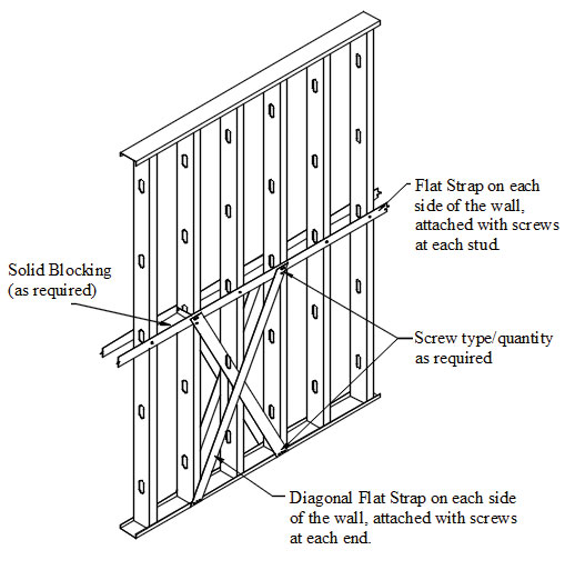
Figure 2. Anchorage of bridging using flat-strap cross bracing.
One of the common methods of bridging anchorage consists of flat-strap cross bracing attached from the bridging line to the bottom of the wall on each side of the stud (Figure 2). The system functions in tension only to transfer cumulative bridging forces to the bottom track and the floor slab; thus a cross bracing pattern is required to anchor stud bridging for buckling in either direction of the wall. For this type of system, the designer should specify the strap size; thickness and width, as well as the connection requirements at both the bridging line and the bottom track of the wall. Stiffness resistance is obtained through a combination of the stiffness of the flat-straps, the stiffness of the bottom track, and the connections between them.
When the bridging member is a cold-rolled channel inserted through the punch-outs of the studs, the concept of anchoring the bridging to the bottom of the wall can also be achieved with a diagonal piece of a stud or track welded to the bridging line and the bottom track, as shown in Figure 3. Welding is typically preferred when wall panels are assembled in a panel shop versus being assembled on site.
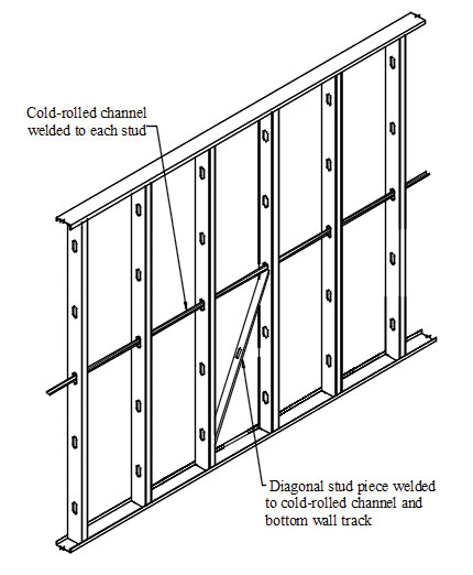
Figure 3. Anchorage of bridging using welded diagonal brace.
An alternative bridging anchorage method consists of a “strong-back” stud oriented so that the strong axis is perpendicular to the bridging row, and attached to both the bridging line and the top and bottom of the wall. The stud acts in bending about its strong axis and transfers the bridging force into the floor slab through a series of clips, as shown in Figure 4. The designer must specify the stud type and connections to be used based on the cumulative force in the bridging line. Stiffness resistance is obtained by a combination of the stiffness of the bridging member, the stiffness of the strong-back stud, and the stiffness of the connection between them. This type of anchorage system may also be used with a flat-strap bridging method by using two strong-back studs attaching the web of the strong-back to the flat-strap on each side of the wall, as well as to the top and bottom track. The two strong-back studs do not need to be at the same location but may be alternated for ease of installation.

Figure 4. Anchorage of bridging using a strong-back stud.
Another method of bridging anchorage is using a built-up stud column placed at specific intervals along the wall length, such as wall openings, as shown in Figure 5. The built-up stud section should be capable of resisting the applied axial load as an unbraced section, as well as resist the cumulative bridging forces within the plane of the wall. Thus, a combined loading condition exists, the applied axial load and the bending loads induced from the bridging row as well as any out-of-plane pressure acting on the built-up column. The use of a weldment or HSS member is an option for the built-up member if larger capacity and stiffness are desired.

Figure 5. Anchorage of bridging using a built-up section.
Bridging anchorage is critical to completing the load path, and ensuring that the tendency of the studs to buckle in flexural and torsional buckling modes is restrained by the bridging. The type of bridging method used will determine the anchorage spacing and the possible anchorage methods. It should be pointed out that the bridging methods that are capable of resisting load in both tension and compression may require a single anchorage point along the wall length. However, tension-only bridging systems always require a minimum of two anchorage locations along the wall length to resist the buckling of the wall in either direction.
For a numerical design example illustrating the design of a bridging member and its anchorage, refer to Cold-Formed Steel Engineers Institute TN W400-16,
www.cfsei.org. The design example provides the detailed calculations for lateral bracing (bridging) and bridging anchorage of axially loaded studs, and compares the AISI S100 and AISI S211 bracing design alternatives available to design engineers. It is shown that in most cases, despite the need to design for larger force when using AISI S211, the more conservative strength requirement in AISI S211 proves advantageous over using AISI S100 for the following reasons:
- Strength calculations for both methods are similar and fairly straight forward, while stiffness calculations can be quite lengthy.
- Stiffness calculations require estimation of the stiffness of the connection between the stud and the bridging, and the connection between the bridging and the anchorage member. Estimation of these values requires advanced analysis and testing, and the data
may not be readily available
for designers. - The accumulation of stiffness for more than a few studs is difficult to achieve with available standard bridging details.▪