
The 1933 Long Beach earthquake showed that unreinforced double-wythe masonry brick walls did not perform well. Consequently, California regulators imposed a requirement that double-wythe brick masonry be reinforced and grouted, and that the newly constructed masonry be destructively tested by drilling a core specimen horizontally through the wall to test the bond between the clay masonry unit and grout for shear capacity. The bond criteria for grout to masonry unit was arbitrarily set at 100 psi. In 1983, the bond criteria was changed to 2.5[pmath]sqrt{f prime_m}[/pmath] psi, a value nearly equal to 100 psi.
Over the past 75 years, the requirement has morphed into application to single-wythe hollow unit masonry walls which was never the intent of the provision and ignores the benefit of webs and tapers in Concrete Masonry Units (CMU). Additionally, there is discussion at the national level on whether or not destructively coring and testing the masonry cores is a worthwhile effort. The following analysis is based on current code provisions and puts the discussion into a rational perspective.
When a reinforced masonry wall is subjected to out-of-plane loads, the tension is carried by the reinforcement and the compression by the masonry. In this context, the masonry is a combination of masonry units, mortar, and grout. There are also shear stresses in the wall. The shear stresses are both perpendicular to the face of the wall, as well as parallel to the face of the wall. The shear stresses parallel to the face of the wall are similar to those that develop between the structural steel and the concrete in a composite steel/concrete slab beam. The stresses in the cross-section are shown in Figure 1.

Figure 1. Stresses in a reinforced masonry wall.
The Masonry Society (TMS) 402 Code, Building Code Requirements for Masonry Structures, requires the wall to be designed to carry the shear forces perpendicular to the face of wall (2013 TMS 402 Section 8.3.5 for Allowable Stress Design, and Section 9.3.5.3 for Strength Design). There are no requirements in TMS 402 with regard to the shear stresses parallel to the face of the wall. However, the California Division of State Architect and the California Office of Statewide Health Planning and Development have requirements for core testing of masonry walls. The minimum average unit shear interface requirement between the grout and face shell has been arbitrarily set at 2.5[pmath]sqrt{f prime_m}[/pmath] psi. This requirement is presumably to verify that there is sufficient bond between the grout and the masonry unit to carry the shear stresses. The coring, shown in Figure 2, demonstrates the destructive nature of the testing. The question is whether this coring is necessary, and whether TMS 402 should even consider a similar requirement.
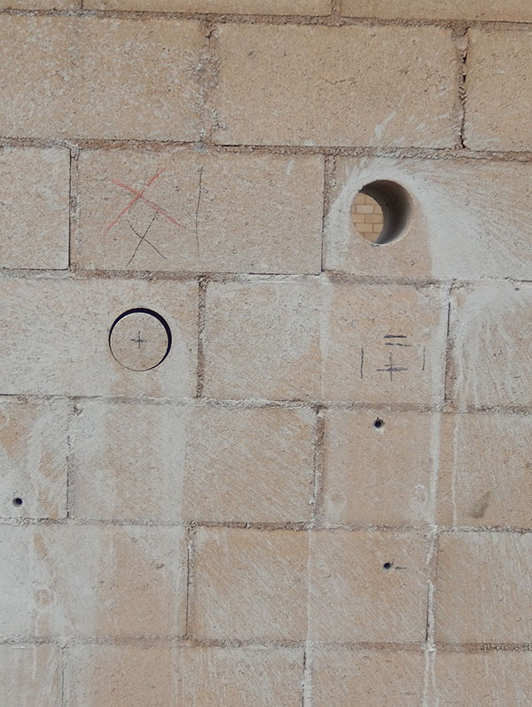
Figure 2. Illustration of the destructive nature of coring. The first attempt hit reinforcement causing further damage.
To answer the question on the necessity of coring, a variety of wall configurations were analyzed. All walls were considered to be fully grouted and simply supported. The analysis procedure was as follows:
1) Select a wall height, block size, reinforcement bar size, reinforcement bar spacing, axial load, and a specified compressive strength, f ‘m. Type S Portland cement-lime mortar was assumed for all walls. Wall weights were determined based on 125 pcf units, although this assumption has a negligible effect on the results. The axial load was assumed to act concentric with the wall. Any eccentricity to the axial load would reduce the out-of-plane load the wall could carry.
In some cases, loads were unrealistically high, being several hundred psf, but the load was still used.
2) The wall was analyzed using the “slender wall procedure”, Section 9.3.5.4.2 of the 2013 TMS 402 Code, to determine the maximum out-of-plane load the wall could carry. In some cases, loads were unrealistically high, being several hundred psf, but the load was still used.
3) Based on the maximum out-of-plane load, the maximum shear force was calculated. From the maximum shear force, the shear stress at the interface between the grout and face shell was calculated. If the wall is treated as a traditional composite section, and the equivalent rectangular stress block is in the face shell, the shear force at the grout/face shell interface will be based on the yield force of the steel. If part of the equivalent rectangular stress block were in the grouted core, the shear stress at the interface would be reduced. The shear stress can be obtained as the shear force divided by the shear area over half the wall height.
Typical results are shown in the Table. The first set of results is for the bar spacing being varied, increasing from 16 inches up to 32 inches. The second set of results is for different height walls. Many other conditions were examined, including varying the axial load, varying f ‘m, varying the eccentricity of the axial load, and examining 12-inch walls with the bars offset from the center. Similar results were obtained in all cases.
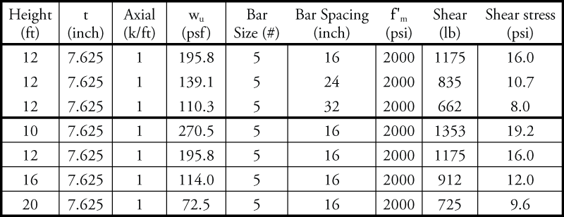
Typical results of analysis of a variety of wall configurations.
A review of these results shows that the shear stress increases as wall height decreases. The highest shear stress is less than 20 psi for a 10-foot high wall, a typical story height. Most masonry walls are at least 10 feet high and the resultant shear stress was for an out-of-plane load of close to 400 psf, an unrealistically high out-of-plane load.
To summarize, the analyses made several conservative assumptions, resulting in a very conservative analysis. To review, the conservative assumptions were:
1) The axial load is considered to act concentrically, resulting in the largest shear force for a given moment capacity.
2) The wall is loaded to the maximum out-of-plane load that it can carry. Typically, due to discrete reinforcement sizes and spacings, and prescriptive reinforcement requirements, walls are not loaded to the maximum out-of-plane capacity.
3) Any interlocking due to offset webs, block taper, etc. was neglected. The shear surface was considered to be planar.
Even with a very conservative analysis, the maximum shear stress was only 19.2 psi. The 19.2 psi was for a 10-foot high wall with unrealistically high out-of-plane loads. Under typical load conditions, the shear stress was 16 psi or less. This shear stress is much less than the 100 psi that was the initial arbitrary California requirement, and also much less than 2.5[pmath]sqrt{f prime_m}[/pmath], which would be about 97 psi for f ‘m = 1500 psi and 112 psi for f ‘m = 2000 psi.
Based on the above results, two conclusions can be drawn.
1) No core testing is required. The shear stresses are very low. Additionally, the above analysis does not consider the benefit of the homogeneous concrete masonry unit which has a continuous connection between the cross web and face shell, taper of the CMU or interlock of overhanging mortar fins.
2) TMS 402 is justified in not requiring designers to check the shear stress at the grout/face shell interface. That will not control the design.
The complete report along with calculations and expanded tables can be viewed online.▪