
A snowstorm in November 2014 hit Northern Oregon and was subsequently followed with freezing rain and arctic temperatures of -20° F. This event caused a large manufacturing plant’s roof to collapse, resulting in extensive structural damage to the facility. Of the 400,000 square foot plant size, approximately 80,000 square feet (20% of the facility) collapsed and shut down the plant’s operations. Structural damage extended to approximately 100,000 square feet of the facility, which was observable by visual means. In this article, the author explores the cause of the failure, collapse load analysis, and provides a brief overview of the structural system that was designed in the 1940s which remained in operation until the date of this event. The U.S. and Canada have thousands of buildings built over 60 years ago that are aging, deteriorating, and experiencing long term fatigue which are prone to failure/collapse. This article explores these issues and offers methods to evaluate existing facilities, which require attention before such fatal events can harm occupants.
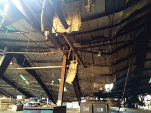
Figure 1
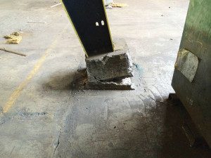
Figure 2
The November 2014 snowstorm was a combination of sudden snow fall, arctic like temperatures, and freezing rain that caused the roof of this steel moment frame facility to collapse. Fortunately, this failure occurred in the early hours of the morning and no fatalities were experienced. Figures 1 through 5 show the extent of the damage and loss of inventory. The building was constructed in the 1940s and comprises approximately 400,000 square feet of space, which was designed through successive permits over several decades. In its entirety, the design of this facility ranges from the 1940s-1960s vintage, and remained in operation until the 2014 storm event.
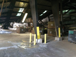
Figure 3.
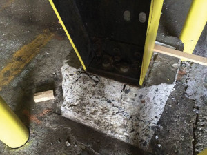
Figure 4.
The ownership of the facility was advised to reduce their occupancy/use of the remaining facility (i.e., “undamaged” sections) until further investigation could be completed. This meant the entire building of 400,000 square feet was approximately 50% shut down due to the possibility of extenuating damage beyond the immediate collapse zone. Specifically, approximately 80,000 square feet was a total collapse, and an additional 120,000 square feet remains suspect or partially damaged, pending further analysis/study. Since this forensic investigation is ongoing, and this is an active file, the details of this study are still confidential. The focus of this article is on the collapse zone, specifically, and recommendations for other facility owners (and their design firms) to take note that such events can occur in their areas, to similar structures that may experience large sudden loading.
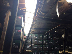
Figure 5
Forensic Investigation of the Roof Collapse
As can be observed from Figures 1 through 5, and after doing a collapse load analysis, the reasons for the failure are attributed to several causes:
1) Excessive snow/ice loading due the storm event that exceeded the capacity of the steel moment frame system.
2) Plastic Hinge Failure at several locations in the steel moment frame system, including compression flange failure of the top chord of the truss.
3) Footing failure at the base reaction.
The structural analysis of the steel moment frame system shows the collapse load is approximately 5 to 7 psf of snow/ice load. This varies somewhat based on the assumption of load distribution. If we assume uniform loading, then the answer will be slightly different from unbalanced snow/ice loading because the load distribution changes the stress concentration points. Figure 6 shows the structural model using RISA 3D and the resultant moment diagram. However, the conclusion from the structural analysis definitively shows that the analytical collapse load agrees reasonably with the estimated ice load at the approximate time of failure during the storm event. The structural analysis also confirms that the collapse load is far below the required design requirement of 20 psf as a minimum snow load capacity, and well below current code requirements, which would exceed 50 psf in certain areas of Northern Oregon.
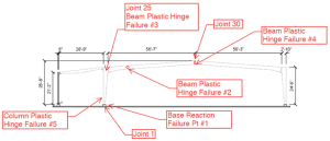
Figure 6
Survey of the Structural Alignment
As part of the structural investigation, the forensic analysis of the cause of failure was performed using analytical methods (RISA 3D) and additionally with a physical geometric survey of the remaining structural frames. In many investigations, engineers can visibly observe the movement of a structure, but in certain cases the misalignment/movement may be too small to detect by visual observation. In these situations, engineers should consider retaining a professional surveyor to perform a physical geometric alignment survey of the structure to provide accurate three dimensional coordinate data of the facility’s main structural frames.
In this case, the structural frames span approximately 100 to 120 feet in length, which translates into deflection criteria of about L/180 ~ 6.7 to 8 inches. This may seem visually observable, but in mathematical terms it’s about 0.5% (0.005) of the length and cannot necessarily be observed with the naked eye. In fact, our investigation utilized a laser system, which in some cases could not measure this alignment because it occurs in three dimensions. The frames can move in three translational directions (x,y,z) and this is very difficult to determine with crude measurement devices such as a plumb bob, laser level, or visual means. The alignment survey of this facility showed certain frames had serious misalignment issues that render them potentially unsafe. This was further compounded by the fact that the collapse load analysis showed the failure deflection was less than 2 to 3 inches on certain moment frames. A low collapse load capacity, which translates into a low deflection tolerance, means that these structural frames are a collapse hazard in storm events and must be retrofitted/repaired.
Conclusions and Application to Other Similar Facilities
There are thousands of facilities similar to this one that are spread across the U.S. and Canada. They are old and designed for a different era of application, and should be investigated for possible premature collapse hazard conditions. The tools utilized in this investigation are readily available and may be implemented to evaluate existing facilities with similar construction so as to forewarn owners of potential hazardous situations.
The use of Forensic Analysis combines the analytical tools of structural modeling with the physical survey tools of measurement devices that can assist structural engineers to better evaluate such failures and prevent new ones from occurring. In this case, the owners are exploring several retrofit schemes to repair the remainder of their facility to retain their occupancy/use, and maintain the safety of their employees.▪