
The U.S. earned a D+ in infrastructure, with bridges scoring a C+ and public parks and recreation a C-. The American Society of Civil Engineers (ASCE) released these grades in 2013 as part of the most recent Report Card for America’s Infrastructure. The grades are based on criteria including capacity, conditions, funding, operational maintenance and future needs.
Parks and recreation contributes approximately $646 billion to the nation’s economy, but state and local budgets supporting these activities continue to decline despite the growing popularity of programs like Rails-to-Trails Conservancy. The organization’s goal is that 90 percent of Americans will live within three miles of a trail system by 2020. The push to expand access to the outdoors means agencies have to tackle increasingly difficult bridge projects while finding ways to trim overall expenses. This balancing act has many organizations taking a harder look at alternatives like Fiber Reinforced Polymer (FRP) composite bridge decks, which tend to last longer than steel or timber and often require little or no maintenance.
Creating successful multi-use pathways can, among other things, include restoration of abandoned structures like the Huntingdon and Broad Top Rail Trail (H&BT) trestle bridge located in Rockhill, Pennsylvania. Built in the 1860s, the bridge spans the Raystown Branch of the Juniata River, the largest and longest tributary for the waterway in south-central Pennsylvania (Figure 1).
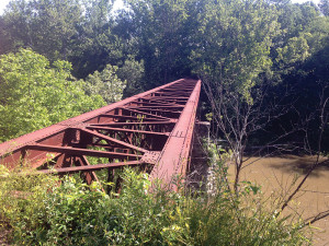
Figure 1. The abandoned H&BT trestle bridge was a bottleneck in the township’s plans to extend its network of trails.
The Broad Top Township’s Board of Supervisors considered several factors to develop an action plan, where future needs called for a bridge deck product with minimal maintenance costs. The new deck had to meet Rails-to-Trails network application requirements for an aesthetically pleasing appearance that could blend with the area’s natural surroundings. Easy installation was equally important, due to the work site’s remote location.
The board evaluated timber and concrete deck options but took notice of a fiberglass alternative due to a nearby trail project. Research confirmed the composites’ corrosion resistance and lighter weight, making a fiberglass deck the frontrunner for the job. An open bidding process identified multiple suppliers.
As a first step, the selected manufacturer (Composite Advantage)identified trouble spots. The deck-to-girder connections proved problematic because, like many railroad bridges, H&BT was constructed with rivet heads on top of its girder flanges. Anchoring the bridge deck to the steel truss was also infeasible due to the amount of corrosion on the aging metal. Rivets and splice plates on the steel structure’s surface created varying elevations. A curve at one end of the bridge added an additional design challenge.
The selected product’s flexibility allowed it to be custom molded to accommodate this bridge structure profile. This made field survey measurements an important component of the design process. In this case, a 2-inch spacer or “step” was integrally molded into the deck’s underside to ensure a flush seating surface that would clear the rivet heads (Figure 2). Because the original superstructure design called for two girders spaced at 10 feet, a 5-inch bridge deck depth was required to span this distance and meet the criteria of 85 psf uniform live load with a maximum deflection of L/500; H-10 vehicle live load; wind uplift load of 30 psf; railing load of 45 lb. per ft.; and deck self-weight of 7 psf. With FRP, the structural properties could be directionally tailored where the H&BT bridge deck was designed for greater stiffness in the span direction versus the longitudinal direction.
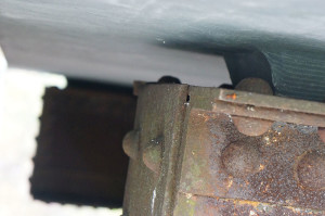
Figure 2. The integrally molded step secures the deck panel to the steel superstructure without the need for secondary shim pieces.
When a project requires additional features like supporting the railing system, these detailing requirements should be coordinated into the deck design and fabrication upfront. Loads generated by pedestrians leaning on the rail were designed to be transmitted through the deck to the bridge superstructure (Figure 3). This approach simplified field work and on-site construction for a significant time savings. Also, incorporating the railing system into the FRP deck eliminated the need to weld or bolt to the existing, historic steel. Pre-fit on the manufacturer’s fabrication floor, the railing was field-installed with nothing more than setting and mounting posts.
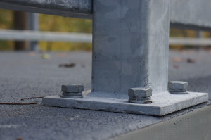
Figure 3. FRP is robust enough to handle rail post attachment load.
Steel bridges are designed to American Association of State Highway and Transportation Officials (AASHTO) standards. There are no applicable design codes for FRP. The material falls instead under an AASHTO special provisions clause, which details allowable stress design and safety requirements. Design calculations and testing correlations were used to determine needed performance properties for each individual project.
In addition to supporting the design gravity loads and limiting deflections, the project called for an environmental durability factor of 0.90. Strains in the panels under dead load only could not exceed 10 percent, and combined dead and live loads could not exceed 20 percent of the ultimate strength of the FRP material. The H&BT deck was designed for a minimum fatigue life of 2 million load cycles.
With conventional structures using traditional construction materials, the engineer of record is typically responsible for the structural design and detailing. Due to the unique nature and performance of composites, the FRP manufacturer generally performs these tasks in-house. In the case of the HB&T bridge deck, a full-scale test was performed to validate the FRP design before submitting findings to the design consultant for final approval, and then to the Pennsylvania Department of Transportation (Figure 4).
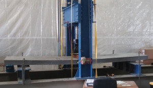
Figure 4. CA performs bending test on FRP deck panel to design loads and safety factors.
The structure was located 400 yards from the trail head. FRP panels and the railing were pre-assembled at the trail head, then trailered through a small canyon to the bridge site. Studs were welded to the superstructure to fasten deck panels to the top of the structure. The lighter weight FRP panels, each 23 feet long by 13 feet wide, were easily moved and placed with a small telehandler (Figures 5 and 6). Total bridge length was 350 feet.
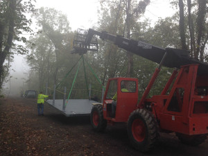
Figure 5. The lighter weight, high-strength FRP panels allow construction workers to maneuver FRP panels to the work site with just a telehandler.
The H&BT is part of a new 4-mile section of public trail that connects Hopewell Borough and Tatesville, and intersects with Riddlesburg and Cooper public parks. The bridge opened in November 2014 (Figure 7). Although the Broad Top board estimated three to four weeks for project completion, with careful preparation and upfront fabrication the use of FRP pared installation time down to just four days.▪
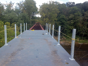
Figure 6. FiberSPAN panels fastened to the top of the bridge’s steel superstructure.
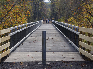
Figure 7. Blending with its natural surroundings, the FRP bridge deck gives pedestrians safe passage across the river and access to new trail sections.