
Part 3: Foundation Revisions
The subject building is an existing timber-framed, multi-story structure that is over one hundred years old. Previous installments of this article have discussed the investigation and resulting need to evacuate the occupants, the nature of the deterioration observed, and the solutions considered for repair of the deteriorated columns. This final part will discuss the impact of the findings of a soil investigation that resulted in the need to develop alternate foundation solutions for the support of the steel jacket column support, and repairs that were required in the building in addition to the column jackets.
Shortly after the repair design was approved by the owner and peer-reviewed by another structural engineering firm, a two-foot-square test pit was created in the basement slab on grade so that geotechnical engineers could confirm the slab thickness and allowable soil capacity assumptions made during the design and analysis phase of the project. This investigation determined that the slab was not six inches thick, and was instead cast in two separate layers for a total of approximately 4½ inches on average, typically 3 inches with a 1½-inch topping. It also determined that the soils in the test pit were extremely soft and filled with slag, and that there were extensive voids underneath the slab that extended several feet in multiple directions. The presence of the voids was attributed to the soil getting washed away by what appeared to be water that was flowing beneath the slab. The presence of water was also consistent with the deterioration of the timber columns below the slab on grade that could be attributed to moisture, rather than insect infestation.
As a result of these findings, it was necessary to abandon the slab on grade as a method of supporting the steel jacket and grillage. Three alternate foundation options were eventually considered: helical piles, compaction grouting under the slab, and conventional spread footings. The use of conventional spread footings was deemed impractical due to the amount of soil that would need to be removed and the adverse impact of excavating several large holes in the basement, which had limited vertical head room. In addition, an evaluation of the soil identified the presence of hazardous materials that would have to be remediated as a part of any excavation.
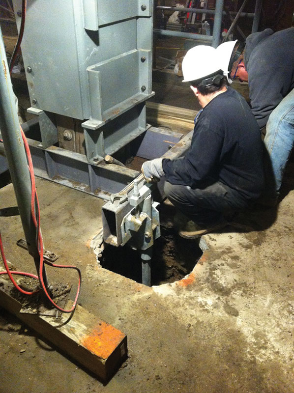
Figure 1
The use of compaction grouting was also deemed impractical because of the expense and difficulty of ensuring that all of the slab voids had been properly filled and the required depth of grout penetration into the upper layer of soft soil had been achieved. Ultimately, helical piles (Figure 1)
were chosen as the preferred foundation option for four reasons:
- The rig used to install the piles could fit within the confines of the basement.
- The capacity of the piles could be easily determined on site, based on the torque achieved during drilling.
- The original steel grillage design only needed to be modified slightly to accept the piles, which in turn did not alter the fabrication of the previously approved steel jacket and channel base assembly.
- The cost of the helical piles was less than the other foundation options.
In order to modify the original steel channel grillage design to accommodate four symmetrically placed piles at each column, HSS steel members were introduced to transfer the reaction of the steel jacket channel bases. The only concern with the pile foundations was the possibility of adverse effects from the vibrations that might be induced from the installation process on the deteriorated columns. In order to mitigate these concerns, the following precautions were employed prior to installing the piles. First, temporary shoring of the columns from the underside of the second floor pillow beams to the basement slab on grade took a portion of the load off the main columns during the construction phase. Second, the steel column jackets, channel bases and HSS grillage had to be erected and in place at each column prior to the installation of the helical piles. The purpose of this precautionary measure was to provide some means of mitigating the unexpected failure of a column by arresting a collapse via the installed steel jacket and grillage sitting on top of the existing slab on grade.
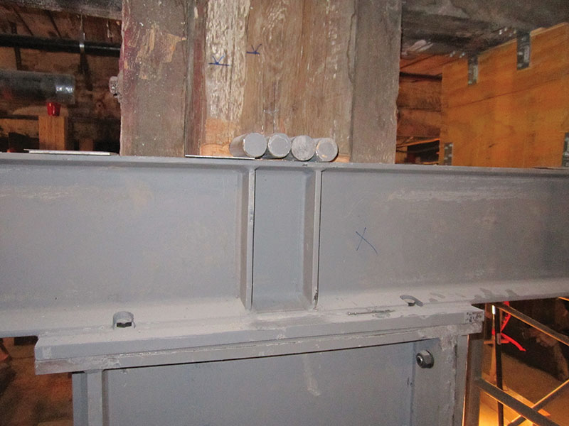
Figure 2
In addition, at the locations where the temporary shoring could not be installed due to the obstruction of a kiln, four of the eight steel “underpinning” rods had to be installed at the top of the jacket (Figure 2). The purpose of this last precautionary measure was to provide some redundancy via partial support of the column by the rods and steel grillage support on top of the existing slab on grade. There were no unexpected problems encountered during the installation of the steel jackets or piles, even though epoxy injection repairs were required at several columns (Figure 3). However, at a few locations, the top of rock was encountered at a shallow depth, which did not allow for the installation of the piles to the required minimum soil depth. As a result, the piles were installed to refusal, then encased in a subgrade concrete pier of a diameter that provided adequate contact area at the top of rock to support the imposed column load.
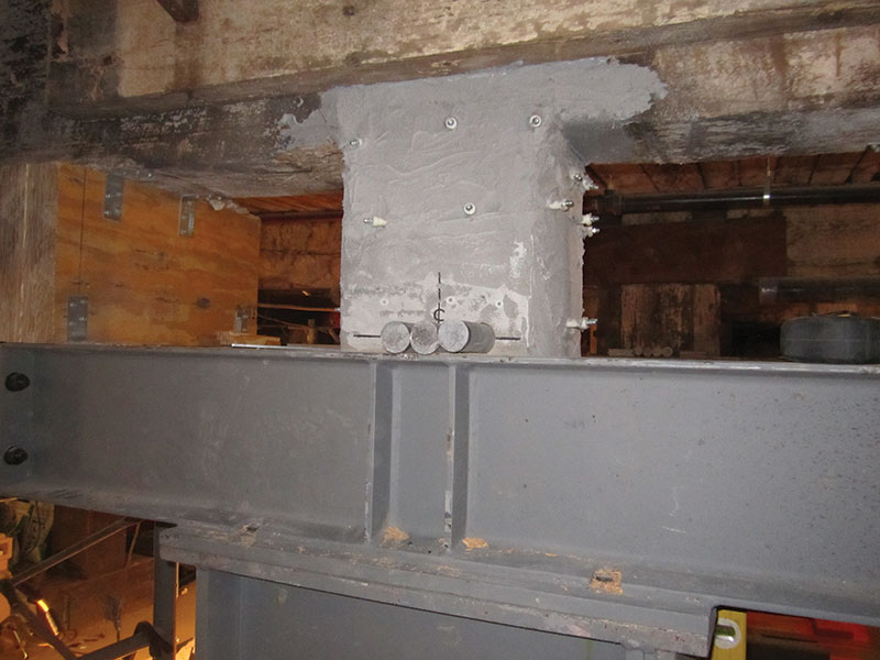
Figure 3
The purpose of the steel column jacket solution was simply to stabilize the building in place, and not attempt to jack the structure back up to its original floor and roof elevations that existed before the column deterioration and settlement began (Figure 4). A similar approach was also taken for the repair of the horizontally distorted column, corbel and beam connection at the second floor. The fix used at the second-floor connection involved installing a stiffened steel side plate on each face of the joint that straddled the timber beam, pillow beam and top of the first-floor column. The side plates were attached to the wood framing via lag bolts, rather than through bolts. Although there may have been hidden mortise and tenon joints connecting each of the three individual timber members together at the joint, the steel side plates effectively stiffened and stabilized the connection.
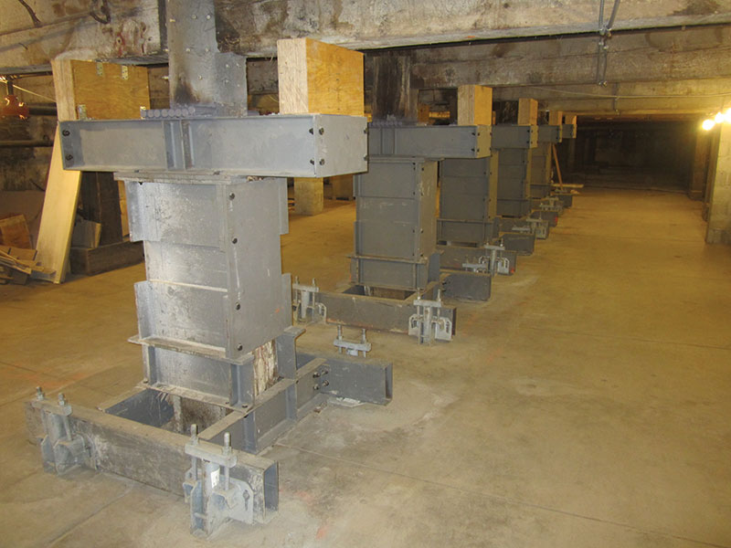
Figure 4
Spanning between the steel side plates, HSS steel members were installed to brace each beam/corbel/column connection and prevent any additional out-of-plane rotation or movement of the joint (Figure 5). The HSS bracing was installed between all of the affected column/beam connections, and extended to an adjacent masonry wall at one end of the glass-blowing room and to a steel column and beam at an adjoining room next to the kiln room. Where the HSS brace was attached to the steel column and beam, the second-floor diaphragm, which was positively attached to the top of the steel framing, was available to resist lateral loads imposed on the line of HSS bracing due to any additional horizontal movement that might occur at the existing distorted column/beam connection. As a result, the existing connections were secured in place, and therefore capable of providing continued structural support of the second-floor framing and bracing of the top of the first-floor column.
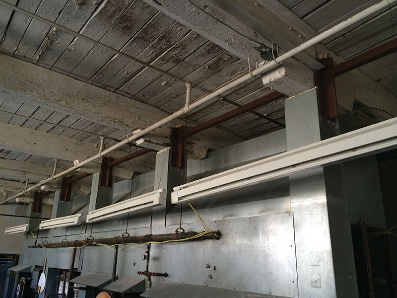
Figure 5
The final remaining repairs associated with the project included minor epoxy injection and/or replacement of some badly damaged timber decking and floor beams. A portion of the credit for the successful implementation of this project can be attributed to the involvement of the contractor, PULLMAN/Shared Systems Technology, Inc. The contractor was selected for this project based on the evaluation team’s previous successful experience with Pullman’s level of workmanship and expertise on similar restoration and emergency shoring projects.▪
Part 1 and part 2 of this series were published in STRUCTURE magazine in the July 2014 and August 2014 issues.