
Delivering Water under Pressure
Installed between 1952 and 1973, the 78-inch and 96-inch-diameter Bay Division Pipelines (BDPLs) 3 and 4 are two of the major regional transmission pipelines in the San Francisco Public Utilities Commission’s (SFPUC’s) Hetch Hetchy Regional Water System. The system delivers water a distance of 167 miles from the Hetch Hetchy Reservoir in Yosemite National Park across California to the Bay Area, and supplies approximately 260 million gallons per day of drinking water to 2.6 million people in the San Francisco Bay Area. Water is critical to the economic viability of the Bay Area, and the public health and safety of those who live and work there.
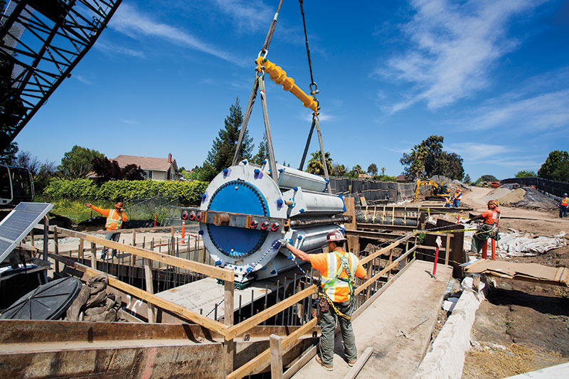
Figure 1. The slip joint was lowered into the vault by crane. Courtesy of San Francisco Public Utilities Commission, Robin Scheswohl.
BDPLs 3 and 4 cross the Hayward Fault at the intersection of a major interstate freeway and a state highway in the city of Fremont on the east side of San Francisco Bay. The 2007 Working Group on California Earthquake Probabilities, made up of the U.S. Geological Survey and partners, estimated a 31% probability that an earthquake of magnitude 6.7 or greater would occur on the Hayward Fault by the year 2036. Studies by Geomatrix Consultants, Inc. (2004) and William Lettis & Associates (2008) concluded that a major earthquake could cause a significant fault displacement at the project site, which would result in certain rupture of both pipelines and extensive localized flooding and loss of water supply to the Bay Area. To address this area of vulnerability in the system, the SFPUC initiated a seismic retrofit program for the two pipelines to ensure that water delivery continues after a major earthquake.
The Program
The first phase of the seismic retrofit program included installing two isolation valve vaults on BDPLs 3 and 4 on either side of the Hayward Fault. This work, which was completed in 2007, provided the SFPUC with the capability of shutting down the pipelines quickly if they rupture at the fault, reducing the extent of flooding and property damage.
The objective of the second phase of the retrofit program, the $78 million Seismic Upgrade of BDPLs 3 and 4 Project designed by URS Corporation (2011), is to ensure continuous delivery of water after a major earthquake. This project spans approximately half a mile between the two previously-constructed isolation valve vaults. The limited 80-foot-wide right-of-way through a congested freeway interchange and residential neighborhood does not allow for both pipelines to be replaced with parallel pipelines while remaining in service. Also, hydraulic studies showed that post-earthquake service could be maintained with only one of the two pipes remaining in service. Thus it was decided that BDPL 3, the older pipeline, will be replaced with a new welded steel pipeline and BDPL 4 will be retrofitted to limit damage and leakage.
Criteria
The seismic design criteria for the project consist of both ground shaking and fault displacement criteria corresponding to a 975-year-return-period earthquake, which is the SFPUC standard for critical facilities that need to be operational within 24 hours after an earthquake. The ground-shaking criteria were developed via site-specific probabilistic hazard analysis considering the Hayward, Calaveras and San Andreas Faults, and numerous other subsidiary faults within 31 miles (50 km) of the project site. The resulting design response spectrum has a zero-period acceleration of 1.05g.
A site-specific study including extensive fault trenching and study of historical records was carried out to determine the fault displacement design criteria. At the project site, the Hayward Fault consists of three distinct traces, Traces A, B and C, with defined primary and secondary rupture hazard zones (Figure 2). To be conservative, it was assumed that all of the expected displacement for a particular trace will occur as a knife-edge displacement anywhere within the primary rupture zone.
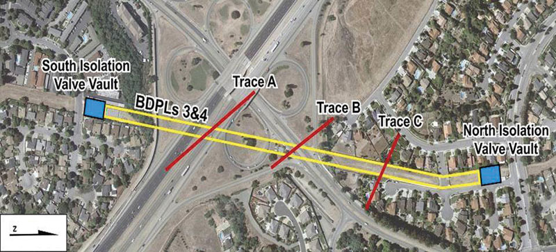
Figure 2. Hayward Fault Traces A, B, and C. Courtesy of URS Corporation.
Trace A intersects the pipelines under a major interstate freeway and has an expected horizontal displacement of 1 foot and vertical displacement of 0.7 feet. Trace B, the main and central trace, crosses the pipe under a state highway (Mission Blvd.) and has an expected horizontal displacement of 6.5 feet. Trace C intersects the pipe in a residential neighborhood and has expected horizontal and vertical displacements of 0.5 feet. In addition to the large expected displacements, the approximately 45-degree angle at which the pipe crosses the fault traces would cause both compression and rotation forces in the pipe which are much more challenging to accommodate than tension.
Solutions
The BDPL 3 replacement consists of installing approximately 2,175 feet of new welded steel pipe (ASTM A1018 Grade 60) with a wall thickness ranging from 1 to 1.25 inches between the two existing isolation valve vaults. The new pipeline has the same inside diameter of 78 inches as the existing pipeline, except for the section that crosses Trace B which is 72 inches in diameter.
Due to the differing magnitudes of expected displacement at the three traces, three different fault-crossing designs were developed. To accommodate the displacements at Trace A, the new BDPL 3 consists of 1.25-inch-thick-wall steel pipe inside of an existing 114-inch-diameter corrugated metal pipe casing under the freeway that provides rattle space for the pipe to flex and bend in response to fault movement. The annulus between the pipe casing and the pipe is filled with low-density cellular concrete. At Trace C, the new BDPL 3 has 1-inch-thick pipe walls and is buried. This new welded steel pipeline was calculated to have sufficient strength capacity for the relatively minor displacements predicted for Trace C.
The large displacement of 6.5 feet expected at Trace B, which would produce a large amount of compression and rotation in BDPL 3, requires a unique and innovative design solution. Design concepts used on previous fault-crossing projects, such as the zig-zag pipeline concept used for the Denali Fault crossing of the Alyeska oil pipeline in Alaska, could not be used for this project due to space limitations. The resulting fault-crossing design consists of new 1-inch-thick wall welded steel pipe with a ball joint on each side of the fault trace and a slip joint to the north, all installed within an underground articulated concrete vault that spans both the primary and secondary rupture zones of Trace B (Figure 3). The design intent is to allow the pipe to rotate at the ball joints and compress at the slip joint to accommodate the fault displacement, while the concrete vault protects the pipe within (Figure 4).
Figure 3. Plan of Trace B fault-crossing. Courtesy of URS Corporation.
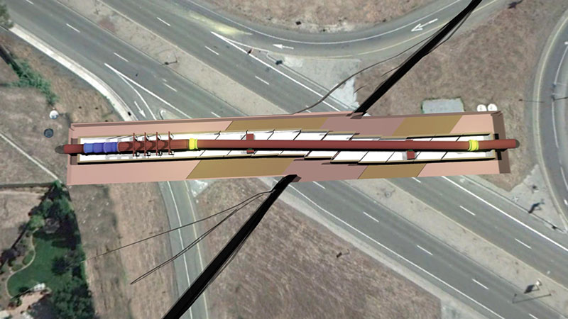
Figure 4. Trace B fault-crossing concept. Courtesy of URS Corporation.
The 20-foot-wide, 18-foot-high, and 305-foot-long articulated vault has 2-foot-thick reinforced concrete walls and slabs and consists of eleven vault segments separated by 6-inch-wide gaps which will allow it to “articulate” to absorb the compression and rotation from the fault displacement. Each vault segment is expected to shift transversely with respect to each other, and to also shift longitudinally to close the gaps. In plan, each of the nine 20-foot-long middle segments is shaped as a 45-degree-angle parallelogram. Both computer analyses by URS Corporation and scale-model laboratory testing at Cornell University showed that vault segments with gaps parallel to the fault perform better than segments with gaps perpendicular to the pipeline.
Inside the vault, the 72-inch-inner-diameter ball joints are installed approximately 200 feet apart and are capable of accommodating 12 degrees of rotation. To the author’s knowledge, these ball joints that were specially fabricated for the project by EBAA Iron, Inc. are the largest ever built. Also specially designed and fabricated for the project, the slip joint is capable of accommodating 9 feet of contraction and 1 foot of extension, as well as an external bending moment of 55 kip-feet and shear of 32 kips which result from the design earthquake. Since no commercially-available slip joints even came close to meeting these specifications, the SFPUC conducted a nationwide search for qualified suppliers and ultimately contracted with Stress Engineering Services, Inc. to design and build the slip joint.
Inside the articulated vault, the pipe is supported on various fixed, sliding, and guided supports. At the sliding supports, the pipe is welded to a steel-plate saddle with a stainless steel bottom sliding surface. This saddle sits on a concrete pedestal topped by a steel plate with a Teflon (PTFE) sliding surface that will allow the pipe to slide in any horizontal direction.
The four guided supports consist of upside-down W-beam U-frames that reduce the bending moment and shear in the pipe, and allow only axial movement of the pipe in the direction of the slip joint to prevent binding. The section of pipe through the guided supports is strengthened with steel stiffener plates and fitted with stainless steel and Hastelloy sliding plates on four sides (Figure 5). The use of the highly corrosion-resistant Hastelloy alloy for the southernmost guided support was necessary to achieve a sliding surface that will maintain its low coefficient of friction long-term in the cold and damp underground vault.
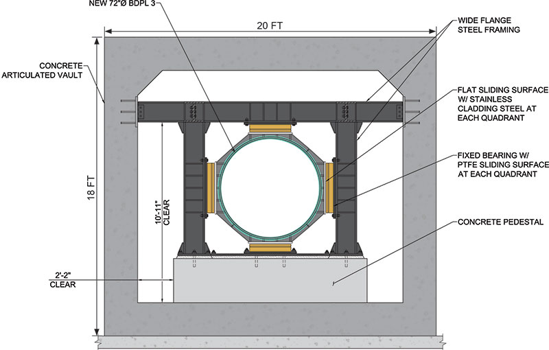
Figure 5. Cross-section of guided supports. Courtesy of URS Corporation.
Analysis and Testing
Since the Trace B fault-crossing concept was newly developed for the project, the SFPUC evaluated its reliability through an extensive program of computer analysis and laboratory and factory testing. Explicit dynamic finite element analyses of the pipeline were performed using ANSYS to capture the effects of sliding friction and large axial pipeline displacements from both fault displacement and ground shaking. Parametric studies were done to test and optimize pipe wall thickness, location and number of ball and slip joints, and location and number of sliding and guided supports. The design objective was a system that would offer a high degree of seismic reliability with relatively low maintenance.
To vet the articulated vault concept, soil-structure interaction analyses were performed using FLAC 3D (Fast Lagrangian Analysis of Continua) which is an advanced geotechnical software program used for continuum analysis of soil, rock and structural support in three dimensions. Concurrently, a 1/10 scale model of the vault was built and tested at the Large-Scale Lifelines Testing Facility at Cornell University. Both the computer analyses and the laboratory testing modeled the 6.5-foot fault displacement and confirmed the individual vault segments would shift and rotate to accommodate the expected ground displacement, while leaving enough rattle space for the pipe within.
Lastly, vigorous factory testing of the ball joint by EBAA Iron, Inc. and the slip joint by Stress Engineering Services, Inc. were performed to demonstrate their behavior under the expected fault displacement. A third full-size ball joint was fabricated for the testing which involved rotating the joint between +8 and -8 degrees while under 200 psi of internal hydrostatic pressure. The slip joint was first hydrostatically tested to 200 psi at the three following static positions: fully extended at +1 feet, fully compressed at -9 feet, and in the as-installed position of zero. Then to prove dynamic performance, the slip joint was subjected to a simultaneous contraction of 9 feet, hydrostatic pressure of 125 psi, bending moment of 55 kip-feet, and shear of 32 kips. The rate of the contraction of the test was 6.25 feet in 2.0 seconds, which is the predicted speed of the fault displacement. Both the ball and slip joints performed as designed. Construction of this project by contractor Steve P. Rados, Inc. began in September of 2012 and is expected to be completed in early 2015.▪