
Imagine reading the front page of your daily newspaper to find out the current bed availability or the number of people on the waiting list for the only hospital in town. Now imagine it is a necessary announcement because this hospital is almost always at full capacity and that the next closest U.S. hospital is an eight-hour plane ride away. Fluctuating hospital availability has been the reality on the remote U.S. island territory of Guam. Fortunately, Guam recently received a much-needed influx of health care professionals and specialists from a newly completed hospital.
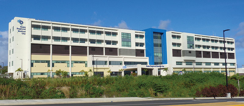
Exterior view of the completed hospital.
Guam Regional Medical City (GRMC) is a new, private, $240 million, 130-bed acute care facility in Dededo, Guam. Located approximately 4,000 miles west of the Hawaiian Islands in the Micronesia region of the Western Pacific Ocean, Guam has a population of approximately 165,000 and a land area of 212 square miles (about three times the size of Washington D.C.). Guam is home to strategic U.S. military installations for both the U.S. Navy and U.S. Air Force. Furthermore, the U.S. Navy is in the early stages of planning for the relocation of 5,000 Marines from Okinawa, Japan.
Completion of the five-story state-of-the-art medical facility overcame several major design and construction challenges: First, Guam is subjected to some of nature’s most destructive forces, including damaging earthquakes, major typhoons, and a corrosive tropical environment. Second, Guam is extremely remote and locally available labor, materials and construction techniques were a major concern in the final selection of the structural systems. Finally, the unique criteria relevant to hospital function, such as stringent vibration control of the floor system, were incorporated through meticulous coordination with the first two challenges.
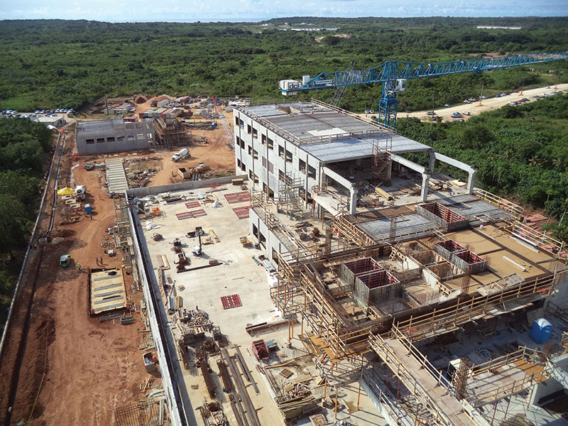
View from tower crane during construction. Courtesy of dck pacific guam, LLC.
Typhoon Winds and High Seismic Requirements
GRMC is designed in accordance with the International Building Code (IBC), 2009 edition, and ASCE 7-05 for a three-second gust wind speed of 170 mph (the highest value included in IBC 2009), seismic accelerations of Ss = 1.50g and S1 = 0.60g and a corrosive tropical environment. Design wind pressures were extremely high as illustrated by the maximum component and cladding wall and roof uplift pressures of approximately 180 psf and 260 psf, respectively. Seismic demands were similarly high and controlled the design of the lateral force-resisting system. The structure was assigned to seismic design category D and had a seismic response coefficient, Cs, equal to 0.25.
The GRMC project reveals that design approaches for dealing with high winds are often at odds with those for handling high seismic demands. One clear example is in the design of the roof structure. Whereas it is advantageous to add mass to the roof in order to counteract the extreme wind uplift pressures, added mass increases the inertial seismic forces that the lateral force-resisting system must resist. Such considerations were carefully weighed and fine-tuned throughout the design process.
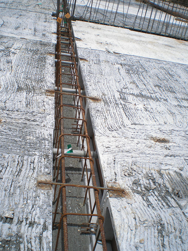
Detail at precast double-tee support to provide continuity.
Constructability and Primary Structural System
Another key consideration from the onset of the project was constructability in Guam. The selected delivery method for the project, construction manager (CM) with a guaranteed maximum price, allowed for direct collaboration between the design team and the general contractor (GC) from the onset of design. For the GRMC project, the CM also acted as the GC. Various structural schemes were evaluated including structural steel, cast-in-place (CIP) concrete and precast concrete. Ultimately, the decision was made to employ a combination of CIP concrete for the vertical framing and precast concrete for the horizontal framing.
Structural steel was considered but eliminated as an option for several reasons, primarily because of shipping costs, the cost of fire protection and the long lead time needed for ordering the material. Another potential risk was the absence of local steel fabricators. Addressing steel related field issues or fabrication errors might create significant schedule impacts if repairs could only be done off-island. CIP and precast concrete, on the other hand, is produced locally. Furthermore, the CM was experienced in CIP concrete and was capable of self-performing much of the CIP concrete work.
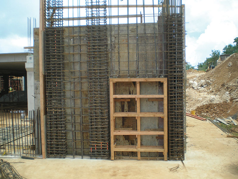
Boundary element reinforcement at the special shear wall.
The final structural framing for GRMC consists of 24-inch deep precast prestressed concrete double tees, precast prestressed beams, CIP columns and walls, and a foundation consisting of spread and mat footings. Although rarely used for hospital construction, precast double tees were selected as the most desirable option for the project. Precast double tees are locally produced in Guam, allowing for shorter lead times and ensuring field issues can be readily addressed. Precast floors also eliminated the majority of horizontal formwork and shoring, increased the speed of construction, and cost less compared to CIP floors. Coordination between the design team, CM/GC, and precaster was critical because prestressed double tee stems allow for less flexibility than other types of floor framing, particularly when considering the layout of MEP systems. To help address this concern, a BIM model was shared between the design team and the CM/GC.
The lateral load-resisting system consists of a building frame with special reinforced concrete shear walls. To provide optimum flexibility, shear walls are primarily located at elevator and stair cores and the short ends of the building. Due to the concentrated high lateral forces, shear walls are 12 inches to 26 inches thick and heavily reinforced. The majority of the concrete shear walls require boundary elements and the end walls contain coupling beams reinforced with diagonal bars. A minimum 3.5-inch thick composite CIP concrete topping over the precast double tees acts as a horizontal diaphragm at each floor/roof level. The reinforcement in the topping slab is designed to transfer all the diaphragm shear forces. Also, chord and drag strut reinforcements are provided to ensure an adequate load path for the inertial floor loads into the shear walls.
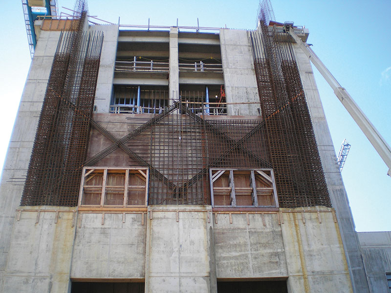
Diagonal reinforcement at the special shear wall.
Vibration Design
Vibration control of the floor structures for both patient comfort and specialized equipment was a critical consideration in the structural system selection. The final selected criteria is summarized as follows:
- Patient rooms (fourth and fifth floors) – maximum peak acceleration = 0.5% of g; maximum vibration velocity = 8,000 µin/second.
- Surgery, operating rooms, etc. (first, second and third floors) – maximum peak accelerations = 0.2% of g; maximum vibration velocity = 4,000 µin/second.
- Vibration limits were based on a “moderate” walking speed.
Vibration criteria were fine-tuned in collaboration with the hospital planner based on proposed usage, future flexibility, cost constraints, and other use issues. In assessing the vibration of the precast floors, “slow,” “moderate” and “fast” walking scenarios were investigated. These separate cases were first evaluated using the structural properties determined, assuming the precaster’s typical details. Next, different aspects of the typical precast details were slightly modified to enhance the vibration control of areas not meeting the selected criteria. Among the detail changes were providing rotational restraint at the ends of the double tees, providing rotational restraint at the ends of the girders, and reducing the widths of the typical 10-foot wide double tee member.
One modification incorporated into the project was to provide rotational restraint at the ends of the double tees, which are usually designed and detailed as simple span members. Instead of typical precast inverted tee beams, the double tees are supported on precast prestressed soffit beams. The double tee prestressing strands extend past the ends of the stems and into the web of the soffit beams that are poured monolithically with the concrete topping. Furthermore, the top of each adjacent double tee stem is tied together across the soffit beam by reinforcement steel welded to embedded plates. This detail was used at the first through third floors to decrease the maximum vibration velocity under a moderate walking pace excitation. Providing rotational restraint at the ends of the double tees decreased the maximum velocity for a typical 37-foot span from approximately 5,440 µin/second to 1,920 µin/second.
For functional reasons, the primary mechanical rooms were located on the third floor which is also the main laboratory level. To isolate noise, shock, and vibration from the primary structure, the large air handling units are supported on a floating concrete slab, which in turn bears on a layer of insulation and fiberglass isolators. A challenge was incorporating the appropriate isolation characteristics and ensuring appropriate stability from seismic overturning forces.
As one of the most remote places in the U.S., Guam is both a strategic hub for U.S. military operations and an exotic island getaway destination. The island is inundated with frequent typhoons and large earthquakes, which its self-sufficient and resilient residents typically take in stride. Much like its inhabitants, buildings in Guam must possess these same traits. Construction of GRMC provides a new world-class hospital designed to withstand the extreme forces of nature and provide much needed alternative health care options for the residents of Guam.▪
Project Team
Owner: Guam Healthcare Development, Inc.
Structural Engineer of Record: BASE Micronesia, Inc.
Special Inspector of Record: BASE Micronesia, Inc.
Architect of Record: Setiadi Architects, LLC
Hospital Planner: Flad Architects
CM/GC: dck pacific guam, LLC
Precast Concrete Supplier: Rocky Mountain Precast