
When designing a column, structural engineers must evaluate the impact of second order or P-∆ effects to determine if loads applied to a structure in its deformed position significantly increase internal forces (i.e. by more than 5%). Typically, second order effects of this magnitude occur when a column is slender; that is, when its height-to-width ratio is greater than approximately 10. If a column is slender, engineers must consider either an elastic second order analysis or they may analyze the column by the moment magnification procedure contained within the Building Code Requirements for Structural Concrete (ACI 318-11). In contrast, engineers would evaluate a non-slender or short column using an elastic first order analysis. The provisions in the moment magnification procedure allow for a column to be designed using a conventional first order analysis provided that the moments calculated by the analysis are increased to account for second order effects. Considerable inconsistencies can exist between the results obtained from an elastic second order analysis and the moment magnification procedure. These inconsistencies cause confusion amongst practitioners and result in wide variations in their use and/or interpretation. Simply put, moments estimated by the moment magnification procedure may be upwards of five times larger than those estimated by a second order analysis. As a result, engineers often discount the moment magnification procedure in favor of the more manageable results obtained from an elastic second order analysis. But the question remains, “Why is there such a large difference within the provisions?”
The main source of these inconsistencies can be attributed to the approximation of a column’s flexural stiffness, EI. The two methods use different base values for stiffness, and then each apply different reduction factors to the stiffness values. Figure 1 presents a summary of the current ACI 318-11 provisions for slender concrete columns. In the figure, the major steps of the slender column provisions are shown as they relate to each analysis method.
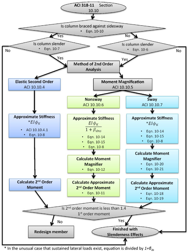
Figure 1: Summary of ACI 318-11 column provisions.
Background
The majority of the current provisions on slender column design first appeared in the 1971 version of ACI 318 as a result of the recommendations of ACI-ASCE Committee 441, Reinforced Concrete Columns. At the time, the new provisions allowed for the use of structural analysis methods made available with the advent of computer analysis software to assess P-∆ effects in slender columns. In lieu of a computer analysis, the 1971 code introduced the moment magnification procedure for approximating slenderness effects. The moment magnification procedure was a replacement for the reduction factor method contained in the previous 1963 version of ACI 318. In ACI 318-63, slenderness effects were accounted for by dividing the axial load and moments by a reduction factor less than one. The reduction factor method was based on the recommendations of Broms and Viest (1961), and added to by MacGregor and Siess (1961). The researchers analytically derived the factor accounting for the inelastic buckling behavior of reinforced concrete. The moment magnification method was based on a similar procedure used by the American Institute of Steel Construction (AISC) for approximating slenderness effects based on Timoshenko’s Theory of Elastic Stability. Overall, the basic premises introduced in the 1971 code are present in the 2011 code with slight alterations based on more recent studies.
The recommendations by Committee 441, and alterations to the code since, are derived from a series of experimental tests performed by several investigators. These tests consisted of eccentrically, concentrically, and laterally loaded sway frames, nonsway frames, and individual columns. Columns were tested in both single and double curvature. Figure 2 presents an example of the test specimens used to develop current reinforced concrete slender column provisions. Researchers have used the data from these tests to support and/or derive stiffness approximations, stiffness reduction factors, sustained load factors, and slenderness limitations.
Figure 2: Experimental Specimens tested by (a) Furlong & Ferguson; (b) Green & Breen; and (c) Ferguson & Breen.
Examination of ACI 318 between 1971 and 2011 indicates that the main source of inconsistency in determining slenderness effects is the approximation of member stiffness, EI. When performing a second order analysis, the EI values used for strength design should reflect the member’s stiffness immediately before failure. At that point, the degree of cracking varies along its length. Thus, the stiffness of the member is somewhere between its gross and fully-cracked moment of inertia multiplied by the modulus of elasticity. Fairly accurate methods exist to estimate the value of EI for a single member, but they are arbitrary for the design of a typical frame when considering the high degree of variability associated with multiple members of varying size, strength, and reinforcement. Therefore, ACI 318-11 provides the following four equations for approximating member stiffness.
EI = 0.70EcIg (Equation 1)
EI = (0.80 + 25[pmath]{A_st}/{A_g}[/pmath])(1 – [pmath]{M_u}/{P_u h}[/pmath] – 0.5 [pmath]{P_u}/{P_o}[/pmath]) EcIg ≤ 0.875EIg (Equation 2)
EI = [pmath]{0.2{E_c}{I_g} + {E_s}I_se}/{1 + beta_dns}[/pmath] (Equation 3)
EI = [pmath]{0.4E_c I_g}/{1 + beta_dns}[/pmath] (Equation 4)
Equations 1 and 2 are permitted for use with elastic second order and sway frame moment magnification analysis. Whereas, Equations 3 and 4 are used solely for the moment magnification procedure. If Equation 2 is used for the moment magnification procedure for nonsway frames, then it must be divided by a sustained gravity load creep factor, 1+βdns. The equations differ from each other based explicitly and implicitly on three variables: a stiffness reduction factor, φk; an approximation of initial effective stiffness, EIeff; and sustained load factors, βdns and βds.
Stiffness Reduction Factor, φk
ACI 318 requires that the stiffness value used for slender column design be multiplied by a stiffness reduction factor, φk, to account for variability in actual member properties and analysis. The code does not explicitly define a φk value. Rather, different values are implicitly included within the provisions. A stiffness reduction factor,φk, equal to 0.875 is incorporated into Equations 1 and 2 and is based on MacGregor’s (1993) recommendations. In Equation 1, the value of 0.70 is the product of both an effective stiffness of 0.80Ig and a stiffness reduction factor of 0.875 (i.e. 0.70 = (0.875)(0.80)). In Equation 2, φk is indirectly included by capping the value to 0.875EcIg. A separate stiffness reduction factor, φk, equal to 0.75 is implicitly incorporated into Equations 3 and 4. For these equations, φk is applied indirectly to the column by multiplying its buckling capacity by 0.75. Mirza (1987) derived this value based on a reliability study.
Approximation of Initial Effective Stiffness, EIeff
Depending on the method of analysis, ACI 318 uses different values and expressions to estimate the stiffness of a column immediately prior to failure. Again, the value of 0.70 used for Equation 1 is the product of both an effective stiffness and stiffness reduction factor. That is, it implicitly assumes the cracked moment of inertia, Ieff, to be equal to 0.80Ig as suggested by MacGregor and Hage (1977). The researchers derived this value based on lateral deflections measured in laboratory test frames (Figure 2). The EIeff used in Equation 2 is explicitly expressed as presented above and includes the influences of member loads and properties including: eccentricity; longitudinal steel percentage, ρ; and the ratio of factored axial load to nominal axial strength, Pu/Po. Khuntia and Ghosh (2004) developed this expression analytically and verified it experimentally. The EIeff used in Equations 3 and 4 is contained in the numerator of each expression. Committee 441 recommended these expressions as lower end approximations of member stiffness. They were developed using a combination of theoretical load-moment-curvature diagrams, analysis of test frames, and computer simulations. Equation 3 is highly conservative for low ρ and low Pu/Po values, but is slightly un-conservative for high ρ and high Pu/Po values. Contrarily, Equation 4 is highly conservative for high ρ and low Pu/Po values, but slightly un-conservative for low ρ and high Pu/Po values.
Sustained Load Factors, βdns and βds
The additional deflections resulting from creep must be accounted for because they will increase second order moments. ACI 318 addresses this issue by dividing the column’s stiffness by the sustained load factor, 1+βdns and 1+βds for nonsway and sway cases, respectively. βdns is defined as the ratio of the maximum factored sustained axial load to the maximum factored axial load, and βds is defined as the ratio of maximum factored sustained shear within a story to the maximum factored shear within a story. In both cases, the loads should be from the same load combination. For all equations, when sustained lateral loads exist (e.g. lateral soil pressure), they are divided by 1+βds. The sustained axial load factor, βdns, is not included in Equations 1 or 2 when performing a second order analysis; however, it is included in Equations 2, 3, and 4 when using the moment magnification procedure. This point is a major discrepancy and point of confusion amongst designers because it often results in significant differences between procedures.
Figure 3: Comparison of ACI stiffness approximations.
Discussion
It is not hard to see that with, all the variations allowed for the aforementioned three variables, many different stiffness values are attainable within each method of evaluation per ACI 318-11. Figure 3 presents a comparison of these differences. The figure shows the ratio of the stiffness approximations in Equations 1 through 4 divided by the uncracked-stiffness, EcIg. These values are plotted as they vary with Pu/Po. Because Equations 2 and 3 vary with ρ, they are plotted once with ρ = 1% and once with ρ = 4% to envelop the practical range. Also, Equation 2 differs with eccentricity ratio, e/h, so it is plotted for an e/h = 0.10 and an e/h = 0.25. From Figure 3 it can be seen that, for most cases, the expressions for stiffness given by Equations 1 and 2 result in higher member stiffness than those given by Equations 3 and 4.
The code provides justification for some of these differences, but not all of them. First of all, though it is not clearly noted in the code, the moment magnification procedure for nonsway or sway frames evaluates a single isolated slender column or single story, respectively. Frequently, an elastic second order analysis evaluates a complete frame. This designation allows φk to take on different values in the different methods based on the conclusion of Furlong and Ferguson (1966) that “frame action as a restraint to column failure resulted in 5 to 15 percent more axial capacity for columns in single curvature than that anticipated for the equivalent isolated columns”. For this reason, a higher φk value of 0.875 is acceptable to use with an analysis that considers frame action. This point is also noted in the ACI 318 commentary.
The source of variation with βdns and βds is less pronounced. Research demonstrates that slender columns subject to sustained loads experienced unstable failure at loads significantly lower than columns without sustained loading – depending on slenderness, eccentricity, and Pu/Po. Other research indicates that sustained loads lead to increased deflections, but any ill effects are offset by normal strengthening of concrete. It is clear that effects of sustained loading must be accounted for in determining slenderness effects, but the translation of this phenomenon to the reduction factors in the code is not clear. The question is raised why sustained axial loads are only accounted for in the moment magnification procedure for nonsway frames. The only justification provided by the code for not accounting for sustained axial loads in elastic second order and sway frame analysis is that the effects of creep are accounted for indirectly by capping the second order moments to 1.4 times the first order moments and that, in this case, a stability check in not necessary.
Conclusions and Recommendations
Through the examination of ACI 318 between 1963 and 2011 and supporting historical literature, several inconsistencies were identified within the current slender column design provisions. Accordingly, the following recommendations are made to clarify and simplify the current provisions. It is important to note that the purpose of these recommendations is not to alter the content within ACI 318-11 but, rather, to clarify and simplify what is currently in the provisions.
- Define the stiffness reduction factor, φk, transparently and include in all stiffness equations as opposed to the current practice of implicitly including within some of the equations and defining in the Commentary.
- Consider removing the stiffness Equations 3 and 4. Currently, the code allows the use of four different EI equations, resulting in highly variable values (Figure 3). Retaining solely Equations 1 and 2 in the code would be a simplification and result in less variation.
- Clarify the use of the sustained load factors, βdns and βds. If βdns is not required for an elastic second order analysis when second order forces are limited to 1.4 times the first order forces, then this point needs to be clarified within the moment magnification procedure. Contrarily, if βdns is required, then this needs to be clarified within the provisions related to performing an elastic second order analysis.▪
References
- ACI Committee 318. Building Code Requirements for Structural Concrete (ACI 318-11). Farmington Hills: American Concrete Institute, 2011.
- MacGregor, J. G., J. E. Breen, and E. O. Pfrang. “Design of Slender Concrete Columns.” ACI Structural Journal 67, no. 1 (1970): 6-28.
- ACI Committee 318. Commentary on Building Code Requirements for Reinforced Concrete (ACI 318-11). Detroit: American Concrete Institute, 1963.
- Timoshenko, S. P., and J. M. Gere. Theory of Elastic Stability. 2nd. New York: McGraw-Hill, 1961.
- Breen, J. E., and P. M. Ferguson. “Investigation of the Long Concrete Column in a Frame Subject to Lateral Loads.” Symposium on Reinforced Concrete Columns (American Concrete Institute) SP-13 (1966): 75-114.
- Green, R., and J. E. Breen . “Eccentrically Loaded Concrete Columns Under Sustained Load.” ACI Journal, November 1969: 866-874.
- Furlong, R. W., and P. M. Ferguson. “Tests od Frames with Columns in Single Curvature.” Symposium on Reinforced Concrete Columns (American Concrete Institute) SP-13 (1966): 55-74.
- Breen, J. E., and P. M. Ferguson. “The Restrained Long Concrete Column as a Part of a Rectangular Frame.” ACI Journal 61, no. 5 (May 1964): 563-587.
- MacGregor, J. G. “Design of Slender Concrete Columns–Revisited.” ACI Structural Journal 90, no. 3 (May-June 1993): 302-309.
- Mirza, S. A., P. M. Lee, and D. L. Morgan. “ACI Stability Resistance Factor for RC Columns.” Journal of Structural Engineering (ASCE) 113, no. 9 (September 1987): 1963-1976.
- MacGregor, J. G., and S.E. Hage. “Stability Analysis and Design Concrete.” Proceedings (ASCE) 103, no. ST 10 (October 1977).
- Khuntia, M., and S. K. Ghosh. “Flexural Stiffness of Reinforced Concrete Columns and Beams: Analytical Approach.” ACI Structural Journal 101, no. 3 (May-June 2004): 351-363.
- Khuntia, M., and S. K. Ghosh. “Flexural Stiffness of Reinforced Concrete Columns and Beams: Experimental Verification.” ACI Structural Journal 101, no. 3 (May-June 2004): 364-374.
- Manuel , R. F., and J. G. MacGregor. “Analysis of Restrained Reinforced Concrete Columns under Sustained Load.” ACI Journal 64, no. 1 (January 1967): 12-24.