
The technological advances in electroslag welding have facilitated its progression from manually fusing vessel joints filled with scrap metal to automatic field-welding of thick steel joints in high rise buildings and long span bridges. The latest version of electroslag welding, ESW-NG (the NG stands for narrow gap – about ¾ inch), is currently accepted by AASHTO for welding common types of bridge steels and is included in the bridge welding code (AWS D1.5: 2010 with interim revisions). This welding method has also satisfied criteria for AISC-defined Demand Critical Welds. A task group is working toward inclusion of ESW-NG welding into the AWS D1.8 Structural Welding Code – Seismic Supplement.
An ESW-NG weld consists of coalesced alloy-cored wire, base metal, and a consumable wire guide. The production of a sound weld requires about one inch of molten slag floating atop a molten weld pool, a motorized flux dispenser, a wire feeder, a water circulator, and a welding power supply. Either a constant potential DC or a square wave AC welding power supply is well suited for the ESW-NG welding process. Containment of the molten weld and slag pools is provided by a sump, run-off tabs, water-cooled copper welding shoes or metal containment plates, and sealant. Welding shoes are detailed for optimal heat transfer and joint orientation. ESW-NG welds are generally single-pass, made in the vertical position, have a deposition rate of about 1 inch per minute, and do not require pre-heat. Defects typically associated with a weld pass, such as slag inclusion and porosity, are very atypical of ESW-NG welds.
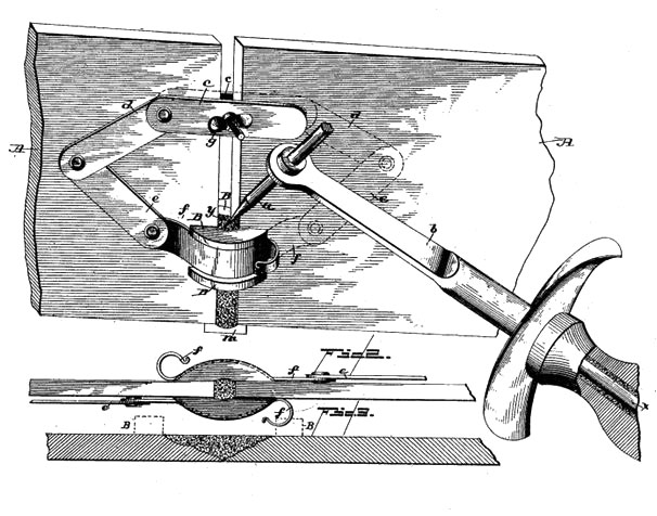
1888 patented welding process resembling electroslag welding used scrap metal as filler material.
Process and Development of Electroslag Welding
An initial arc is necessary to commence the ESW welding process. The arc is soon extinguish by pre-deposited flux. Electric current passing through the slag pool creates a molten resistor that is heated to approximately 3500°F. Hence, ESW is considered to be resistance welding.
Advancements made in ESW to achieve the superior physical properties of ESW-NG focused on electrode chemistry, wire guides, flux maintenance, welding shoe architecture, management of heat transfer during the welding process, and automation.
Modern electroslag welding: ESW-NG.
ESW Wire Guides and Flux Maintenance
During the ESW welding process, wire must be guided into the weld cavity. Consumable metal guides replaced non-consumable guides early in the evolution of ESW. As an ESW weld progresses vertically, a stationary wire guide and the wire it is channeling are melted. Metal guides must not make contact with the walls of the joint, which would cause an electric short-circuit.
The Linde Division of Union Carbide (Linde) and the Hobart Brothers Company (Hobart) were issued patents that focused on round guide (“guide tube”) profiles. Linde developed a flux-coated consumable guide tube. The coating insulated the guide from the walls of the joint. Using Linde’s process, the guide tube’s flux liquefaction was unpredictable and the slag pool depth was difficult to manage. A single-wire stationary guide within an ESW weld cavity could create a weld of reasonably uniform properties in joints of up to approximately 2 inches (50 mm) thick. To ensure an even deposition of weld metal across thicker joints, Hobart developed a method of oscillating consumable guides. This method incorporated insulating rings, which prevented electric short-circuiting. An experienced welding operator added flux according to the sounds emitted from the weld pool. Flux was added when the operator heard the weld excessively arcing. If the weld became too quiet, too much flux had been added.
Round guides evolved into flat guides housed with channels for feeding one to multiple wires. These guides eliminated the need for oscillating guides and opened the door for narrowing the welding gap of conventional ESW, from approximately 1.25 inches (32 mm) to ¾ inch (19 mm) used in ESW-NG.
Contemporary ESW-NG incorporates automatic wire feeding and flux dispensing. The wire feed rate is synchronized with guide consumption. About ½ of the required starting flux is added to the welding sump before the commencement of welding. The balance of the starting flux is gradually added during the first minute of welding. As welding progresses vertically, traces of flux plate the walls of the welding shoes. Automatic flux dispensers maintain a constant-depth slag pool by monitoring variations in electric current and potential. Flux addition is generally very small and constant. The required amount of flux is about 0.2 ounces (5.5 g) per minute.
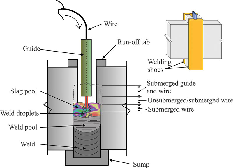
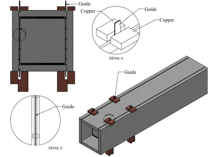
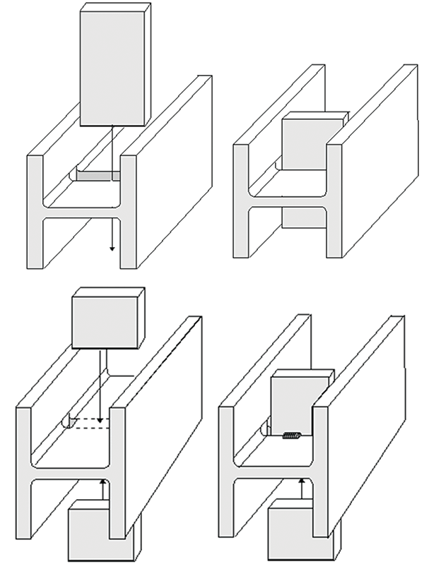
Cross-section of an ESW-NG joint during fabrication and isometric of the contained joint.
Welding Shoes and Management of Heat Transfer
Side containment has always been used to construct an ESW weld. When possible, ESW-NG welding shoes are constructed of copper, which has very high thermal conductivity – allowing rapid heat transfer from the base metal. Additional heat retardation is provided by coolant, typically water, that circulates through the channeled body of welding shoes. ESW-NG copper welding shoes are fabricated from solid 1-inch (25 mm) thick copper plate. The finished products are at least 4 inches (100 mm) wide and 12 to 18 inches (300 mm – 450 mm) long.
Although rapid heat transfer from the base metal is desirable, if heat escapes from the molten flux and weld pools too rapidly, the weld cross-section will be of exaggerated barrel-shape, or worse, incomplete fusion at the weld corners can occur. The architecture of ESW-NG welding shoes promotes complete and uniform fusion of the weld and base metals across its width. A tri-part welding shoe (Tri-part Shoe) incorporates several features that enable complete fusion at the weld’s corners. A version of the Tri-part Shoe, the Tri-part Articulated (Flex) Shoe, has a flexible enter section that allows the welding shoe to fit snugly against misaligned plates. There are also welding shoes for welding plates of different thickness and a welding shoe for welding T-joints. Welding shoes have also been designed for oblique-angled joints.
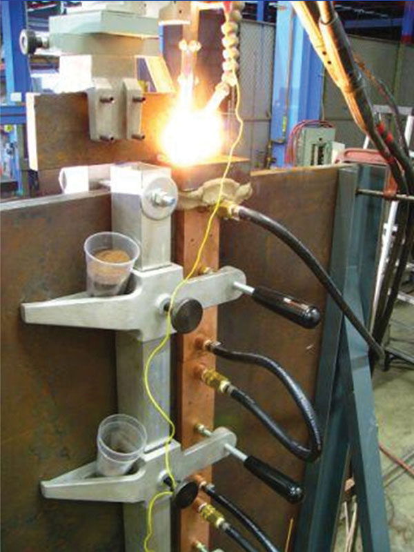
Box column diaphragm ESW-NG welding.
Electroslag Welding in the Shop
ESW-NG welds thick plates and cross-sectional elements [from about 1 inch (25 mm) to 6 inches (150 mm) in thickness] much more efficiently than traditional multi-pass arc welding processes such as flux-cored arc welding. However, ESW-NG requires the force of gravity and more instrumentation than conventional arc-welding processes found in the field. Hence, ESW-NG welding has seldom been seen at a construction site, until recently.
Shop-Welding of Stiffener, Continuity, and Base Plates
The joint formed by a stiffener, continuity, or a base plate and a flange of a wide-flange shape is a T-joint. As welds increase in thickness, so does the expense of typical arc welding processes, because these welds must be made in multiple passes and require preheat.
Currently, three stiffener plate configurations are available to ESW-NG welding. The traditional option requires a 180 degree rotation of the girder after completion of welding the first stiffener plate. By fabricating beveled slots entirely or partially through the web of the girder, the need to rotate the girder during stiffener plate welding is eliminated. These slots also have the added advantage of relieving residual stresses existing in rolled shapes near their fillet “k” area.
Column stiffener plates were welded with the traditional ESW process in Northern and Southern California buildings prior to 1980. The October 17, 1989 Loma Prieta and January 17, 1994 Northridge earthquakes provided real-world comparisons of all of the welding processes used to fabricate steel structures in California. Not one failure or crack propagation was discovered in any of the ESW welds inspected.
Stiffener plate topology for ESW-NG welding that does not required 180 degree rotation of the girder. Wire guides pass through pre-fabricated slots in web.
Box Columns Fabrication
The welding of diaphragm plates to the interior walls of box columns using arc welding methods is labor-intensive, particularly welding the final of the four welds needed to attach these plates. With the introduction of ESW’s “key-hole” welding method, this process was made simpler. Holes are cut through two parallel box column plates in line with the centerline of the seam weld gap, where a sump and run-off tabs are installed. A wire guide is inserted to commence the ESW welding process. The vertical rate of rise required to produce a sound keyhole weld is about 1 inch per minute (26 mm/minute). Today, not just the final, but all diaphragm welds of box columns may be quickly made using ESW-NG.
ESW-NG was recently used to weld BRB gusset plates to plates embedded in the concrete core of the Wilshire Grand Hotel in downtown Los Angeles.
Taking ESW-NG to the Field
Rarely was conventional ESW seen at the site of a major structural engineering project. One notable ESW field application occurred during the construction of the New Orleans, Louisiana Mercedes-Benz Superdome, circa 1975. With the immergence of ESW-NG, electroslag welding is now a highly-competitive option for welding thick steel joints in the field.
East Span, San Francisco – Oakland Bay Bridge Tower
The first ESW-NG field-welding occurred during the construction of the East span of the San Francisco/Oakland Bay Bridge (complete early in 2014), the world’s longest self-anchored suspension (SAS) bridge. The base of its single tower consists of twenty (20), 33-foot (10 m) long ESW-NG welds that join steel plates, up to four inches (100 mm) in thickness. Five uniquely oriented joints required custom welding shoes. Thirty-six-foot (11 m) long guides channeled two 3⁄32-inch (2.4 mm) diameter alloy-cored wires into the molten slag and weld pools as three shoes on each side of the joint were leap-frogged in unison ahead of the pools. The ESW-NG welds were completed in 60 days. Less than 5% of the total length of the welds required repairs. Weld defects were generally due to variations (on the shallow side) in the optimal slag pool depth.
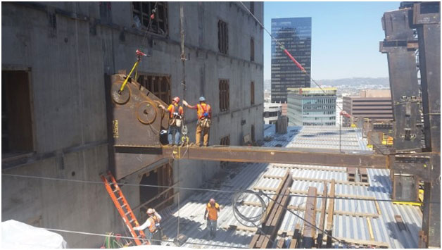
The Wilshire Grand Hotel, Los Angeles, California
The tallest skyscraper in California, The Wilshire Grand Hotel, is under construction in downtown Los Angeles. Its lateral force resisting system consists of a concrete core, buckling-restrained outrigger braces (BRBs), and perimeter belt trusses. ESW-NG welds joined gusset plates for Lower Outrigger BRBs to the structure. These BRB ESW-NG joints are approximately 12 feet high x 2.75 inches thick (3.6 m x 7 cm). ESW-NG welds up to 49 inches (149 cm) long and 5 inches (15 cm) thick also joined the flanges of the chord and diagonal members of the Lower Belt truss to the face of box columns.
This issue contains an article on the Wilshire Grand and two prior issues (December 2014 and August 2015) of STRUCTURE tracked construction of the Wilshire Grand.
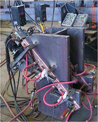
Mock-up of instrumented column flange splice. Traditional horizontal FCAW column splices can be rapidly welded at 45 degrees using ESW-NG.
General Field-welding of Building Structures
ESW-NG is poised for common use in the field-erection phase of steel construction. It is particularly ideal for welding heavy column flange splices of large W-shapes, since joints oriented 45-50 degrees from vertical can be successfully welded with ESW-NG. It takes 30 hours or more to splice a heavy-column using FCAW. In comparison, it takes about 30 minutes or less to weld both flanges of any thickness material using ESW-NG.
Conclusion
Electroslag welding may no longer be considered as simply one option to splice thick plates in a steel fabrication shop. It can economically weld stiffener, continuity, and base plates to the flanges of steel shapes, and attach diaphragms to the inside walls of box columns. Modern technological advances in ESW, embodied in ESW-NG, has also expanded its role to the construction site of a major high-rise building and bridge construction. ESW-NG is proving itself to be the most cost-effective choice at many connections, for the reliable production of thick welds in steel bridges and buildings.▪