
Mies van der Rohe’s famous maxim, “Less is more,” clearly applies to the pipe bridge recently built across the Tujunga Channel in the Lake View Terrace area of Los Angeles to supply recycled water to the Hansen Dam Municipal Golf Course. Overall simplicity and sparing use of material contribute to what strikes many as an elegant appearance.
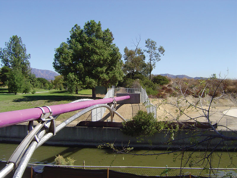
View of the completed crossed arches pipe bridge.
The bridge is part of the Hansen Dam Golf Course Water Recycling Project of the Los Angeles Department of Water and Power (LADWP). The Hansen Dam Municipal Golf Course will soon join several other golf courses, cemeteries, parks, and nurseries in the LADWP service area that use recycled water for irrigation of large areas of turf or other landscaping. The view of the pipe and bridge also illustrates why LADWP staff often refer to recycled water projects as “purple pipe projects”.
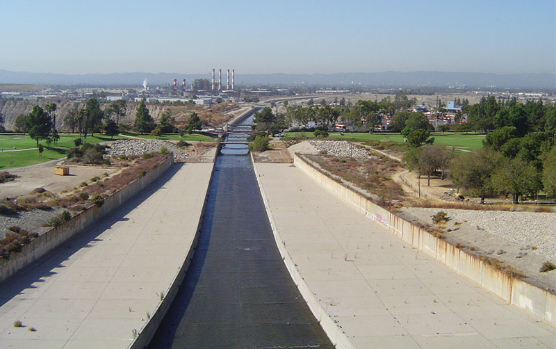
Three bridges crossing the Tujunga Channel: golf cart bridge, crossed arches pipe bridge, and rubber dam maintenance bridge. Red and white stacks in background are at Valley Generating Station, site of the recycled water Hansen Tank and Pumping Station.
Bridge Design
Owned by the United States Army Corps of Engineers (USACE), the Tujunga Channel conveys storm water out of the Hansen Flood Control Basin to nearby spreading grounds that recharge the San Fernando Groundwater Basin or on further to the Los Angeles River. The Los Angeles County Flood Control Districts (LACFCD) also regulate work within the channel right-of-way. These two agencies established a number of design goals and requirements for the pipe and bridge.
- easement for the pipe and bridge as narrow as possible
- minimal surcharge to the channel walls from the bridge footings
- shortest possible construction duration
- strong preference that no construction equipment enter the channel
- requirement for twelve foot vertical clearance to the channel
The Hansen Dam Municipal Golf Course is on USACE-owned land leased to the City of Los Angeles Department of Recreation and Parks. Golf course management requested a low profile for the bridge and pipeline. The design also was shaped by the LADWP Water Distribution Division’s desire for low maintenance and long service life of the bridge and pipeline.
Bridge designer William W. Lai, P.E., of LADWP’s Civil & Structural Design Group, came up with the novel concept of crossed arches after wrestling with the problem of how to provide resistance to lateral loads, including seismic. Instead of inserting braces between the arches, crossing the arches provided an efficient way to resist lateral forces. The use of arches allowed the design of drilled pier foundations that fit within the narrow right-of-way available.
The decision to use pipe for the arches stemmed from a desire to use type 316 stainless steel throughout the bridge structure to prevent corrosion. The number of structural shapes available in stainless steel is limited, but pipe is readily available. Pipe is also more easily bent to radius compared to some other structural shapes.
The Tujunga Channel is 60 feet wide at the bridge crossing. The bridge span is about 82 feet. The bridge carries a 128-foot length of epoxy-coated 20-inch diameter welded steel pipe which weighs about 28 kips when filled with recycled water. Concrete thrust blocks are provided at each end of the water pipe where it bends down 45 degrees to join the buried ductile iron pipeline. The geometric layout of the bridge arches was calculated using analytical geometry formulae in an Excel spreadsheet. Stress analysis was performed with RISA 3D software. Stress levels in the stainless steel were limited to about 60 percent of the values allowed for carbon steel. The governing load was full dead load, which produced mostly compressive forces with some bending. None of the structural capacity of the welded steel water pipe was considered in design; all loads were assumed to be carried by the arches. Seismic forces induced cyclic load reversal resulting in tension and compression; torsion and bending stresses were minor.
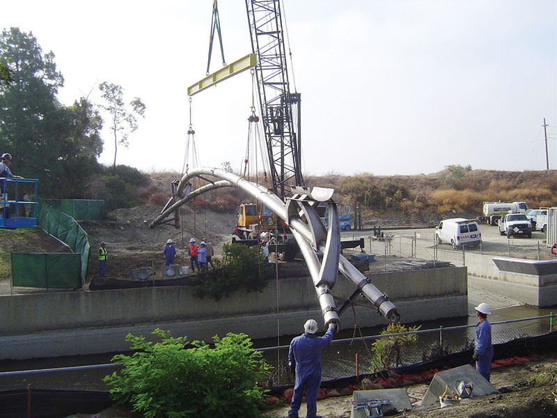
American 7150 Mobile Crane hoists completely assembled crossed arches pipe bridge into position.
The crossed arches were designed from 10-inch diameter pipe with full penetration butt welds and pinned end connections. Pin-like connections were also designed for the two crossing points. The two connecting structures from the arches to the recycled water pipe, dubbed “the chairs”, each have four legs supporting half-cylinder pipe seats with clamp straps over the top of the pipe. Each leg is an H-shape with 6-inch flanges and a web tapering from 14¼ inches to 3½ inches. The chairs were fabricated by cutting, rolling, and then welding ¼-inch plate. The chair legs are tapered from their bases on the arches to the seats for the water pipe, and the weak axis of the section follows a curved path. The chair legs see moment at their bases and axial force along their length. The seats are lined with neoprene to help prevent galvanic corrosion between the water pipe and the chairs, and also to shield the water pipe from excessive vibration and contact stress.
The two chairs and two end thrust blocks divide the water pipe into spans of approximately 37 feet, 54 feet, and 37 feet. The total bridge steel weight is about 12 kips. The design was modeled and turned into drawings using AutoDesk REVIT Structure software. This approach worked so well that shop drawings were not necessary and all model dimensions were within 1/8 inch of the drawing dimensions.
Yousef A. Gobran, P.E., of LADWP’s Geotechnical Engineering Group, designed four reinforced concrete drilled pier foundations topped with rectangular pile caps sloped at a 45 degree angle. Each drilled pier is 36 inches in diameter and 21 feet deep, and resists the applied loads by skin friction. The out-to-out width of the bridge and foundations is only ten feet. Jianping Hu, Ph.D., P.E., G.E., also of the Geotechnical Engineering Group, used Sigma/W 2004 software to provide the USACE with a finite element method soil stress analysis to demonstrate that forces transmitted to the walls of the Tujunga Channel from the piers were within acceptable limits.
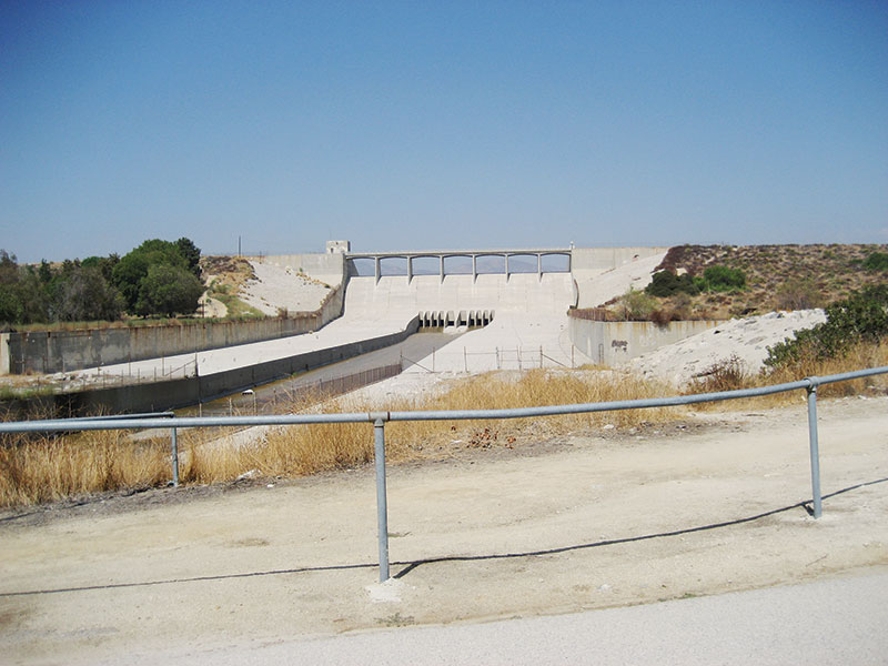
Spillgates of the Hansen Dam, source of the Tujunga Channel, upstream of the crossed arches pipe bridge.
Bridge Fabrication
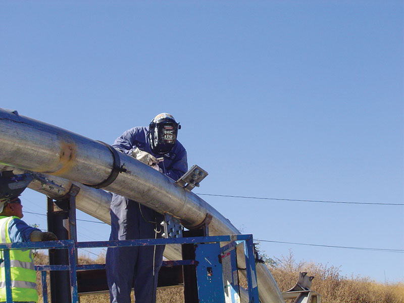
All fabrication, except rolling the pipe arches to radius, was by the LADWP’s Structural Steel Shop. The 10-inch diameter pipes were rolled to a radius of 86 feet by Marine Valve and Supply Co. of Whittier, California. The bridge, including the chairs, was completely assembled and welded in the shop, except for the mid-span welds. The shop designed and fabricated temporary supports and braces to keep the bridge arches properly positioned, and LADWP surveyors verified that the alignment was correct.
Bridge Construction
LADWP’s Integrated Support Services Division (ISS) built the foundations, erected the bridge, and installed the recycled water pipe and thrust blocks. Each arch was trucked to the site in two pieces. They were then attached to the same temporary supports and braces used during assembly in the shop, surveyed again, and the final center-span welds were made in the field. The completely assembled bridge and the temporary braces were then hoisted into place across the Tujunga Channel with a mobile crane. No equipment entered the channel, as requested by the Regional Water Quality Control Board. The value of prior shop assembly and surveying was confirmed when the bridge was placed and fastened to the foundations on the first attempt. A dual baseplate system was used. One set of baseplates, including leveling nuts, was attached to the anchor bolts on the piers. A second set of baseplates with brackets was pinned to the ends of the arches and then field welded to the first set of baseplates. Once the baseplates were welded, the temporary braces were removed. Then the water pipe was installed on top of the bridge, followed by construction of the reinforced concrete thrust blocks at the ends.
Site preparation and foundation work for the bridge began in March 2011. The pipe bridge superstructure was erected and the recycled water pipe was placed on it in August and September 2011. Construction of the ductile iron pipeline began in September 2012 by LADWP’s Water Distribution Division. Construction of the pumping station by ISS will begin in March 2013. The initial purpose of the project is to deliver about 500 acre-feet per year of recycled water for irrigation of the Hansen Dam Municipal Golf Course. However, the pipeline and pumping station were sized anticipating customers in addition to the golf course.
Temporary plates, braces, and supports help to fit up the mid-span weld of the crossed arches pipe bridge.
Conclusion
Bridge designer, William Lai, believes that the design concept for the small crossed arches pipe bridge over the Tujunga Channel can be scaled up for longer spans and heavier loads. He also believes that the concept could be adapted to loads other than pipe, e.g., a road deck. Until recently, the authors were unaware of other examples of bridges with crossed arches. The December 2012 issue of STRUCTURE magazine features the award-winning Tempe (Arizona) Town Lake Pedestrian Bridge, designed by T.Y. Lin International, which prominently utilizes crossed arches to support the pedestrian deck.▪
Project Credits
Project Owner, Engineer, and Constructor: LADWP
Fabrication: LADWP Structural Steel Shop
Pipe Bending: Marine Valve and Supply Co., Whittier, CA
Bridge and Pumping Station Construction: LADWP Integrated Support Services Division
Pipeline Construction: LADWP Water Distribution Division