
Bridge historians and early textbooks generally call a truss with alternating compression and tension diagonals a Warren; however, sometimes it is called an equilateral truss since all panel lengths and diagonals are of equal length creating a series of equilateral triangles. When the panel lengths are shorter than the equal length diagonals, it was sometimes called an isosceles or isometric truss.
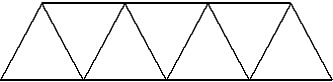
Figure 1. Commonly accepted Warren Truss.
When the span length increases and the height of the truss necessarily increases, the long compression members in the top chord need bracing to minimize buckling in the vertical direction. In this case, verticals are placed from the lower chord panel points up to the mid point of the chord member directly above. In addition, the deck structure stringers get longer requiring either heavier members or the addition of verticals from the top chord panel points dropping down to shorten panel lengths.
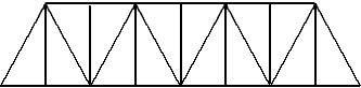
Figure 2. Warren Truss with verticals to support top chord and deck structure.
Neither of these truss styles are what James Warren and Willoughby Monzani patented in 1848 in England. They based their patent on similar trusses that were built in France by Alfred H. Neville and a patent that was granted in England to William Nash in 1839 on a similar design. Warren and Monzani were well known English engineers, and their design was for a truss that could be used as a deck or a through truss. They used cast iron for the top chord, and diagonals and wrought iron bars and links for the lower chord members. The top chord cast iron members were connected through cast iron junction blocks, and the cast iron diagonals and lower chord wrought iron members were connected with pins. The title of the patent application was Construction of Bridges and Aqueducts and was issued on August 15, 1848 with Patent #12,242. Their profile was rectangular. Even though Squire Whipple in the United States had published the method of determining loads in truss members under uniform and varying loads, this method had not made its way to England. It wasn’t until 1850 that W. B. Blood developed a method of analyzing triangular trusses, as Whipple had.

Figure 3. Warren and Monzani patent drawing showing deck at both levels.
Warren and Monzani’s patent stated,
The specification of this invention exhibits four different modes of building bridges, which it is stated may, with some slight modifications, be applied to the construction of aqueducts and roofing.
1) The bridge is built with cast iron side bands, rods, or plates, inclined towards each other, and combined so as to form a series of Vandykes [V shapes]. They are bolted at top to horizontal compression rods, and at bottom to horizontal tension rods, and carry a roadway at top or at bottom, or at both.
2) Or the bridge may be built of cast iron side angular frames (placed with the apices [point] downwards), which have their bases bolted together, end to end, and their apices bolted to horizontal rods.
3) Or, instead of the preceding modes of longitudinal construction, hollow cast-iron transverse frames may be employed, which are inclined, and bolted together at top, and are similarly attached at bottom to horizontal rods, bars, or plates.
4) Or wrought iron tie rods may be bolted at top to compression rods, and at bottom held together by the side of wooden girders, and the structure strengthened by means of stay rods. The angles of the plates are regulated by longitudinal screw rods and nuts.
It is clear they didn’t size their members or give details as to the load, either tension or compression in their diagonals. He didn’t even think of his web members as triangles but only connected VanDykes (V’s) between a compression member on top and a tension member on the bottom. They had four claims as follows,
1) The mode of constructing bridges, aqueducts, or roofing with iron rods, bars, or plates, inclined towards each other, and connected together at top by compression band, and at bottom by tension band, so as to carry a roadway at top or bottom, or at both.
2) The mode of constructing bridges with cast iron angular frames bolted together at their bases, and having their apices bolted to horizontal compression rods.
3) The mode of constructing bridges with transverse hollow cast iron frames inclined towards each other, and bolted together at top and at bottom to horizontal plates.
4) The mode of constructing bridges with wrought iron rods inclined towards each other, and attached at top and bottom, as described.
It appears their only claim to originality was in the use of triangles with top compression chords and lower tension chords. The first major bridge, built by Joseph Cubitt in 1852 roughly to the patent, was the Newark Dyke Railroad Bridge of the Great Northern Railroad. In it he used alternating cast iron compression and tension diagonals with cast iron upper chords and wrought iron links for the lower chord. At the middle panel he had opposing cast iron members.
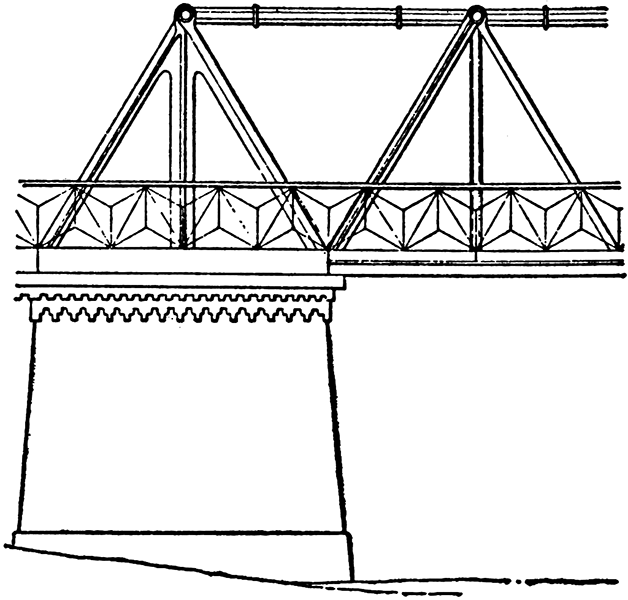
Figure 4. Newark Dyke Bridge, cast iron A-frame on pier.
The bridge crossed the Dyke on a sharp angle, requiring a span of 240 feet 6 inches. Cubitt said the Warren design was brought to him by C. H. Wild. He wrote,
Each girder consists of a top tube, or strut of cast-iron, and a bottom tie of wrought-iron links, connected together by alternate diagonal struts and ties of cast and wrought iron respectively, dividing the whole length into a series of equilateral triangles, of 18 feet 6 inches length of side.
These girders rest on the apices of cast-iron A-frames, placed on the masonry of the abutments (Figure 4). Each pair is connected by a horizontal bracing at the top and the bottom, leaving a clear width of 13 feet for the passage of the trains…
The trusses are so arranged, that all compressive strains are taken by the cast-iron, and all tensile strains by the wrought iron; the strains, in all cases, in the direction of the length are of the respective parts, and all cross strain is avoided. The parts are so proportioned, that when loaded with a weight equal to one ton per foot run, which considerably exceeds the weight of a train of the heaviest locomotive engines in use on the Great Northern, or on any narrow-gauge line, no tensile, or compressive strain on any part, exceeds five tons per square inch of section.
It is clear that by 1852 Wild had taken the Warren configuration and, applying Blood’s method of analysis, calculated the load in each member so that it could be proportioned properly. An end view of the bridge showed, however, the hugeness of the members which was typical of English and European bridge design at the time. Over time, the bridge style was converted to all wrought iron with built up riveted members.
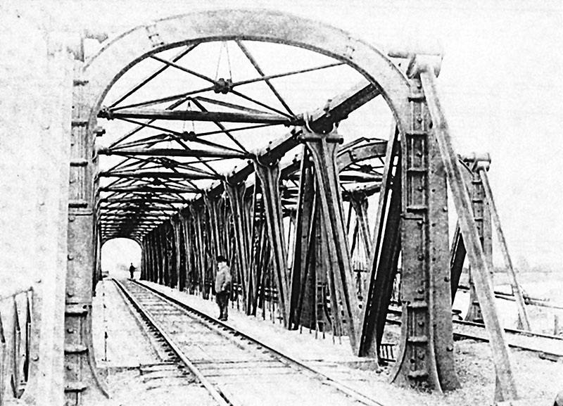
Figure 5. End View of one of the two parallel Newark Dyke Spans. Note massiveness of cast iron members as well as the verticals to support the deck at mid panel points.
In the United States, the Warren/Wild/Cubit design was known by our engineers. Many of them subscribed to the Proceedings of the Institution of Civil Engineers where Cubitt had published his article. Prior to 1848, Whipple had designed and built similar trusses on the New York and Erie Railroad and discussed them in his 1846/47 book on bridges. He included the plan shown in Figure 6.
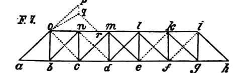
Figure 6. Whipple plan for a bridge similar to the Warren Plan with inclined end posts.
Not only did he design this span, he built several for the New York and Erie Railroad in 1848, the same year Warren got his patent in England.
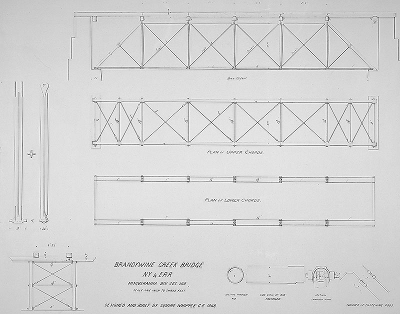
Figure 7. Whipple’s Brandywine Creek Bridge, New York and Erie Railroad, 1848.
In an article in Appleton’s Magazine and Engineers Journal in January, 1851, he described some of his New York and Erie bridges and wrote,
These were wrought-iron skeleton girders upon the triangular plan, such as have since been called Warren girders, and by some regarded as a newly invented combination. But they are merely trusses with parallel chords and diagonals, or rather, oblique members, with only one series of obliques, and without verticals, except to concentrate weight upon the obliques from intermediate points along the upper or lower chord, according as the girder is loaded at such upper or lower chord.
Whipple did not think there was anything new with what was being called a Warren Truss. In fact, in his 1846/47 book he wrote of trusses without verticals. He called this a “cancelled truss which dispenses with vertical pieces, except perhaps at the ends, or at the first bearing points from the ends.” He found, in fact, that a truss, his trapezoidal without verticals, used 8% less iron.
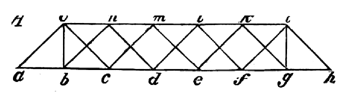
Figure 8. Whipple Plan 1846 but bridge historians call it a Double Warren Truss.
Several trusses that were patented in the United States incorporated the alternating tension and compression diagonals associated with the Warren Truss. The first was a wood and iron rectangular truss by A. D. Briggs in 1858 (#20,987) followed by Alber Fink in 1867 (#62,714) with a combination wood and iron trapezoidal truss with equilateral triangles with verticals dropping down to support the deck at mid panel points. He wrote, “I adopt the triangular, system of bracing between the two chords, both because this system best avoids evils arising from the unequal expansion of a wrought-iron bottom and wooden top chord, and because it is the system of bracing having the least amount of material for equal strength with other systems.” In the same year, J. Dutton Steele (#63,666) received a patent for an Isometric Truss. He had been building them since 1863 and called it an isometric plan, as the diagonals were of equal length with a shorter panel length. He had Charles Macdonald write a long report comparing all of the standard bridge designs, including the Pratt, Howe, Whipple and Warren trusses. Macdonald concluded the only cost savings in a truss bridge are in the web members, as the top and bottom chord requirements were the same for most bridges. For a standard bridge span length of 165 feet, he determined the Howe trusses needs 54% more iron in the web and the Pratt needs 31% more iron than the Isometrical truss. He then compares the Isometrical truss with Linville’s double intersection truss and determines the isometrical uses 19% less iron in the web. He presents the results of a study by C. Shaler Smith in 1865 where he compared the Fink, Bollman, Triangular (Warren) and Murphy Trusses. Smith determined the Triangular and Murphy were more efficient than either the Fink or Bollman trusses for both through and deck trusses. His conclusion stated the Isometrical Truss required less iron in the web system than any other trusses considered. In addition, he found the Isometrical Truss was, especially in wood, much easier to adjust in the event of wood shrinkage.
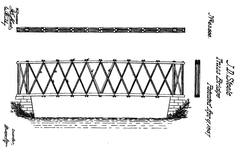
Figure 9. J. Dutton Steele patent drawing for an isometric plan.
In 1872, Whipple, in an article in the Transactions ASCE entitled “On Truss Bridge Building,” wrote that he had objections to Macdonald’s pamphlet and how he used the Whipple Double Intersection truss in his comparison, stating: “Now, Mr. Macdonald represents what he designates as the ‘Whipple Truss,’ with diagonals inclining only 30° from the vertical. I desire here to enter my emphatic protest against the imputation of ever having tolerated any such practice.” He then got into the Isometric Truss (and the Warren style), writing:
But what of the Isometric? The name, at least, as applied to bridge trusses, is new, and euphonic [pleasing to the ear] withal. This is a truss with parallel chords without vertical members in the web: one of the general types discussed and compared in my publication of 1847 with reference to Fig. A., page 14…
I am not aware that there had existed any examples of the parallel chord truss without verticals, prior to their construction by me over 20 years ago, with the important exception of the plank lattice bridge. This was first known to me under the name of “Town’s Lattice Bridge,’” and it was a very cheap and serviceable bridge when properly constructed…
But somehow it occurred to me…that a plan in which every member of the web system should do something in the way of advancing the weight toward the abutments, might possess advantages over one having vertical members merely to transfer the action of weight directly from chord to chord without advancing it at all horizontally…
The Trapezoidal truss, with and without verticals, though depending upon combinations so old that “the memory of man” (especially the present generation) “runneth not to the contrary” still, perhaps, owes something to me for economical form and proportions…
These gentlemen [Macdonald and Merrill] are pleased to term ‘The Whipple Truss;’ and considering that the Isometric and the Post [with inclined posts] trusses are merely modifications (and not very favorable modifications either) of a type of truss first used and thoroughly discussed by me.
It is clear that Whipple believed that the Warren or Isometric trusses were simply extensions of trusses he wrote about in the 1840s, and built in the 1840s and 1850s. In an article on the Pratt Truss (STRUCTURE, May 2015), a case was made that the trusses called Howe and Pratt should really be called Whipple Trusses. A similar case is made here that the Warren Truss should really be called a Whipple Truss. The reasons are that Warren, when he developed his truss, did not know how to size his members nor could he distinguish between tension and compression in his web members. He never designed or built a truss with an inclined end post nor a truss with verticals. A truss as he patented it was never built. Whipple on the other hand had analyzed, designed and built trusses with various web members and inclined end posts prior to Warren’s patent.
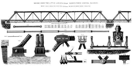
Figure 10. Little Juniata Bridge, Pennsylvania RR, cast and wrought iron with verticals, Pony Truss ~1870.
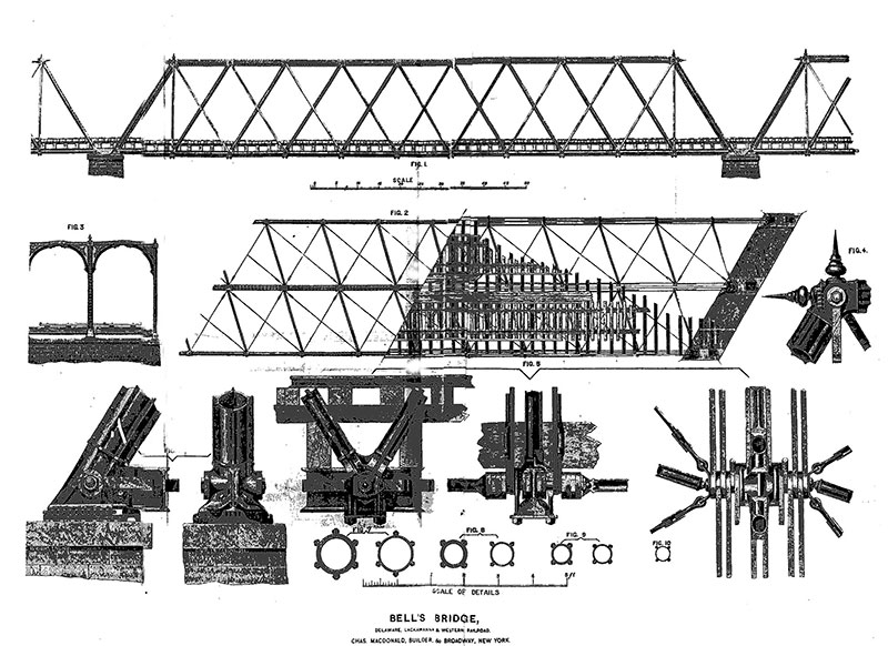
Figure 11. Bell’s Bridge, Delaware, Lackawanna & Western RR 1872, Double Warren or Whipple.
It is probably too late to change what most people call the various trusses, but it should be at least recognized that most of the truss patterns used in the late 19th and 20th century had their origins in the United States and Squire Whipple between 1841 and the 1880s. What were called the Warren trusses were built in the thousands as short span pony trusses with no verticals, longer spans with verticals, even longer spans with double intersections, and still longer spans with subdivided panels. They were originally built with cast and wrought iron members with pins and, later, with wrought iron members and cast iron joints with pins, and later fully riveted in steel. Polygonal top chords were also added in many trusses to extend the span length. J. A. L. Waddell used the pattern in many of his lift spans after the turn of the century. Several examples of the bridge style are shown in Figures 10, 11 and 12.▪
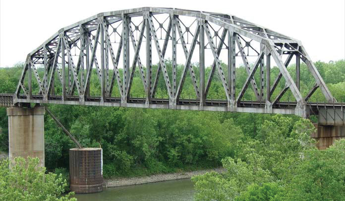
Figure 12. Warren, Isometric, Truss, Polygonal top chord, with verticals, all riveted steel bridge for BNSF Railroad over Verdigris River, Oklahoma~1960.