
Stone is one of the oldest construction materials used by man, as well as the longest lasting building material available. Whether stone structures were built to provide shelters, aid agriculture, or provide a passage over an obstacle such as a river, a valley, etc., they have made a significant contribution in shaping the cultural landscape of countries around the world. In the United States, many examples of stone arch bridges can be found, still accomplishing their original function of bridging streams and rivers. Many people recognize the need to preserve these historic structures, as they are part of the history and heritage of many local communities. This goal should be balanced with the need for safe roadways and bridges. The preservation and rehabilitation of historic stone arches involves many steps and parties. This article focuses on the structural evaluation and assessment aspects of the preservation. From the design professional side, a successful outcome starts with the structural engineer recognizing that, even though these structures were not designed to perform under modern traffic loads, they can still perform well due to their inherent strength and durability.
Historical background
Compared to other countries with a long tradition in masonry construction, the inventory of masonry arch bridges in the United Stated is rather small. According to the 2013 National Bridge Inventory (NBI) there are 1699 masonry bridges in the U.S., of which nearly 93% are on roads other than the National Highway System. These bridges are typically on lower volume road systems that are not eligible for federal funding. Detailed records for masonry railroad bridges are not as readily available, but it seems likely that there are at least as many masonry railroad bridges in service as the NBI reports for roads.
Of the current NBI masonry bridges in service, 50% were built prior to the end of 1910: half of the masonry bridges in use are more than 100 years old. This compares with 1% of the in-service concrete bridges, 4% of the in-service steel bridges, and 3.5% of the in-service wood/timber bridges having been constructed before 1910. It is clear that most masonry bridges have exceeded their intended service life. As a result, many masonry arch bridges have functional issues including inadequate width, non-compliant guardrails, etc. but remain in service due to their critical location, cost of replacement, community involvement or historic designation.
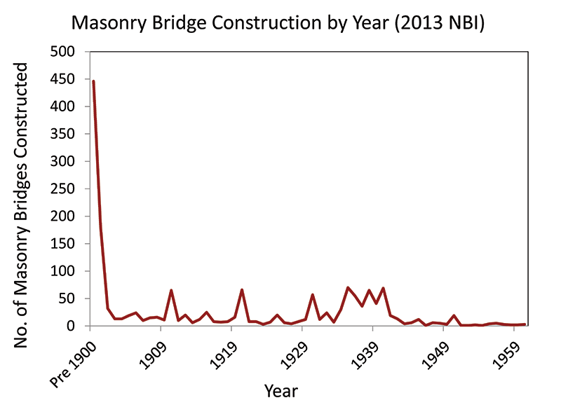
Masonry bridge construction over time in the U.S. Construction of new masonry bridges dropped off dramatically at the beginning of the 20th century and essentially stopped at the outset of World War II.
The majority of the existing masonry bridges are concentrated in the northeastern part of the country where European settlers, who brought the technical skills required for the construction of the arches, first arrived. Location and technological innovation affected their spread as well. Higher concentrations are found where construction material (i.e. stone) was readily available. Since the first bridges were built in the early colonial years, American engineers had a relatively short timeframe to implement the design and construction of stone arch bridges before the advance of alternative materials, such as iron, steel, and reinforced concrete, made stone obsolete. Still, engineers had a preference for stone when performance and durability were more important than cost and efficiency. Masonry arches were the primary choice for railroad bridges well into the early twentieth century, where the need to carry heavy train loads was met by the excellent structural capacity of the stone arch.
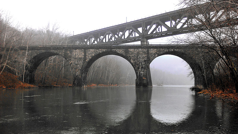
Six-span, railroad stone arch bridge constructed in 1907 over Conemaugh River, Pennsylvania. It was later replaced by a new steel truss bridge when the railroad was realigned due to construction of the Conemaugh River Dam.
Dry-laid construction was likely used for most of the early bridges, when the available mortar in the U.S. was not suitable for this type of construction. Lime mortar was common in masonry construction until late-nineteenth century, before the spread of hydraulic cements. Because of its low compressive strength, slow hardening, and tendency to dissolve in a harsh environment, lime mortar was not well-suited for stone arch bridges. Considering also its self-draining feature, dry-laid masonry was somewhat superior to wet-laid, or mortared, masonry in the early age of stone bridges. With the introduction of better performing mortars, the wet-laid construction typology took over and allowed engineers to design larger and more durable bridges. Most of these dry-laid early bridges have been lost, and the majority of the stone arch bridge inventory in the U.S. comprises mortared masonry.
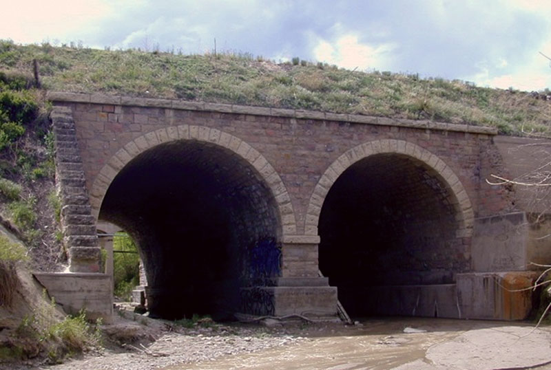
Two-span, stone arch bridge constructed in the late 1880s over Cottonwood Creek in Colorado Springs, Colorado. It served as a railroad bridge until the early 1960s when the tracks were abandoned. It was re-opened to vehicular traffic in 2012 after a restoration project.
Evaluation and Assessment
Design professionals play a key role in the preservation of stone arch bridges. The crucial question the structural engineer is often called to answer is: “What is the capacity of the existing bridge?” Defining the load carrying capacity of stone arches is a challenging task. There is not a widely accepted analysis procedure among the engineering community, and structural engineers approaching this problem face a set of challenges that starts with the lack of information on how the bridge was constructed. Typically, construction documents, such as plans and specifications showing geometry and materials used in the construction, don’t exist. The analysis itself is complicated by a number of unknown factors including the contribution of spandrel walls to the stiffness of the arch barrel, interaction of the barrel with the fill, fill properties, and the effects of material degradation or cracking in the barrel. Further, material properties are unknown unless a significant effort is expended to test the compressive strength, tensile strength, and elastic modulus of the masonry assemblage. Fill properties are rarely investigated.
The first step towards a successful structural assessment is the field investigation of the bridge. Significant properties to investigate are the overall geometry, thickness of the arch barrel, and materials used in the construction. Of great importance is the assessment of damage in the existing structure that could impact the capacity of the bridge. Common distresses include stone deterioration, mortar weathering, cracking in the arch barrel and spandrel wall, and displaced stone units. Efflorescence at the underside of the arch barrel is an indication of insufficient drainage within the arch. The trapped moisture has the potential for material damage in cold climates due to freeze/thaw cycles.
Longitudinal crack below spandrel wall, at junction with barrel vault.
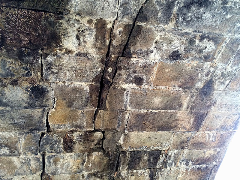
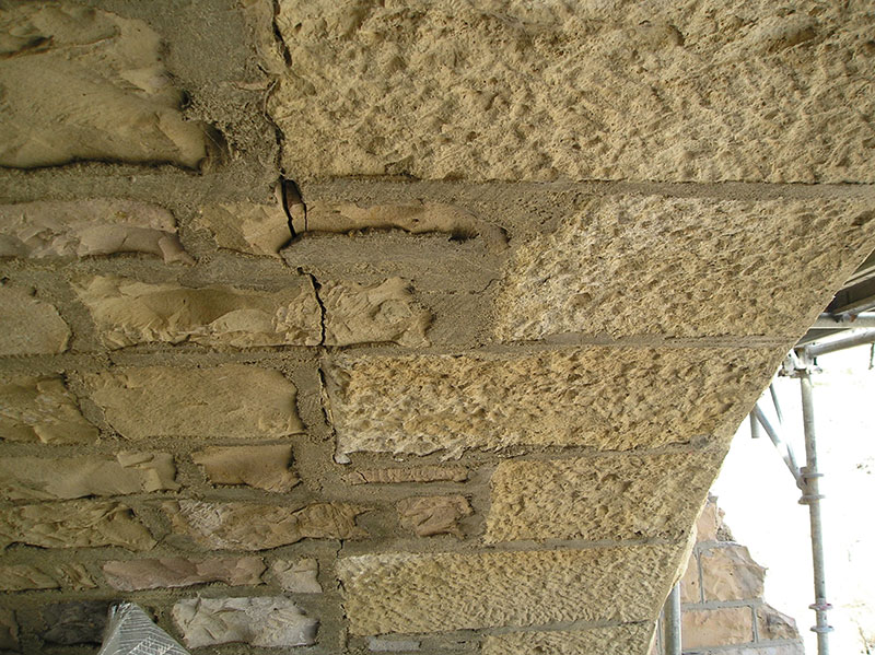
Large longitudinal cracks at stone arch intrados.
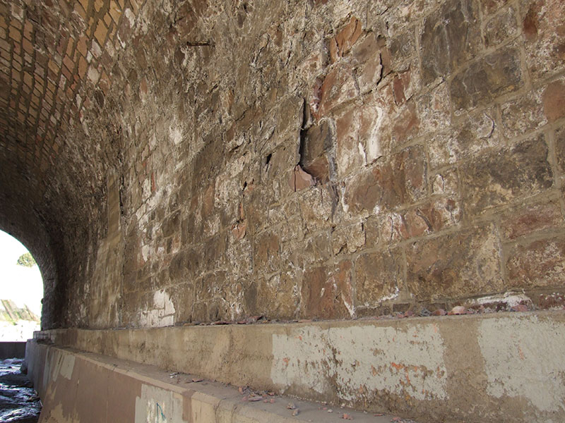
Stone spalling and deterioration due
to freeze/thaw.
Nondestructive Evaluation (NDE) techniques can provide valuable information to support the analysis of masonry arch bridges. Microwave radar, also referred to as Surface Penetrating Radar (SPR), can be successfully used to determine the arch thickness and investigate the integrity of the barrel vault. Details about voids within the masonry, loss of cross-section, the configuration of the fill, and the presence of anomalies or utilities buried in the fill can be obtained with low-frequency microwave radar. Infrared thermography can provide information on moisture profiles in the masonry leading to diagnosis of the extent of damage caused by excessive moisture or saturated freeze/thaw conditions. Stone and mortar samples can be collected and tested for mechanical properties and mortar composition.
A live load test is also a valuable tool for the evaluation and rating of stone arch bridges. The structure can be directly rated to a particular live load in what is generally called “proof testing”. This approach runs the potential for inelastic responses and the possibility of imparting damage to the structure if the bridge is required to function under a very heavy vehicle. From an investigative standpoint, a “diagnostic” approach is preferred. The diagnostic method uses a vehicle load well below the maximum capacity of the structure but still capable of generating a significant live load response in the bridge. The structure is instrumented using surface-mounted strain transducers and Linear Variable Differential Transformer (LVDT) displacement sensors. The sensors are concentrated at key locations, such as the arch mid-span (crown) and quarter-points. The data collected during the test is generally used to calibrate a finite element model of the structure that can then be used to develop accurate load ratings for a large variety of vehicle classes. Another key aspect of the live load test is the use of a slow-moving vehicle that allows for a complete response history, or “influence line,” to be collected.
All of the steps described above are taken to improve the confidence level in the evaluation of the load carrying capacity of the bridge. Engineers who have confidence in their information are less likely to make overly conservative assumptions.
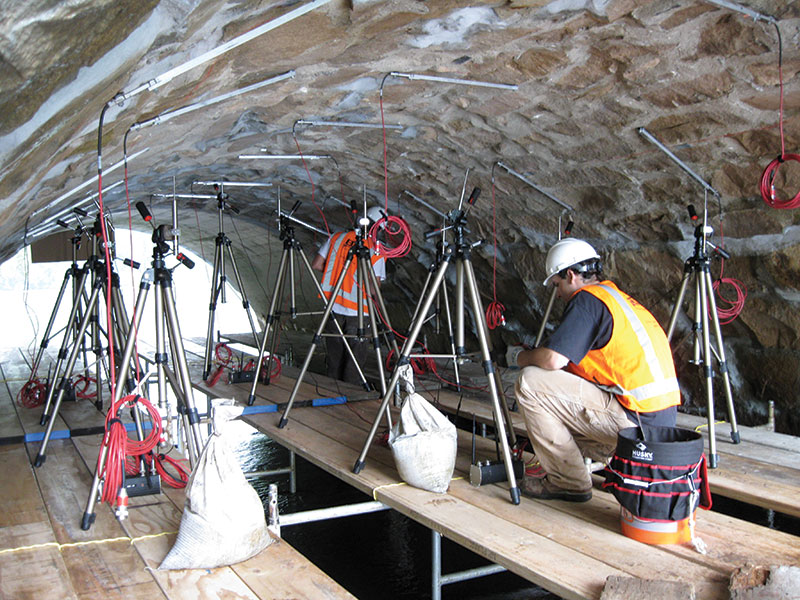
Typical live load test instrumentation layout, with LVDT sensors and strain transducers installed on the underside of the arch barrel.
Analysis and Load Rating
Stone arch bridges can be analyzed using different analysis techniques. The most common are: semi-empirical methods such as the MEXE method; plastic limit analysis methods (three hinge and rigid block); and, the Finite Element (FE) or Discrete Element (DE) methods. Semi-empirical methods are conservative in nature and should only be used as screening tools. Limit analysis methods provide a more refined analysis and are appropriate for most structures. The FE method is suitable for all structures, including problems involving complex geometry or load conditions and evaluation of various strengthening options. Modeling of distress conditions, such as material deterioration, spandrel wall separation, and longitudinal cracks is also possible. This, however, results in very complex models that are difficult to validate and, as such, should only be performed by experienced engineers.
The American Association of State Highway and Transportation Officials (AASHTO) Manual for Bridge Evaluation (MBE) addresses the load rating of unreinforced masonry arch bridges and, according to the MBE, masonry arch bridges are evaluated at the Inventory Level only. The intent of rating at the Inventory Level is to determine the live load at which the structure can be safely used for an indefinite period of time, that is, without damaging the structure. The AASHTO rating procedure also requires the load-carrying capacity to be evaluated using the Allowable Stress (AS) method based on limiting the tensile and compressive stresses that develop in extreme fibers under a combination of axial and bending forces. An axial force-bending moment interaction diagram is typically used to accomplish this task. Failure modes due to instability should also be investigated. Allowable inventory compressive stresses for different types of masonry construction are provided in the MBE. Yet, no allowable tensile stress values are provided, and there is a lack of direction in the manual on how to evaluate this property. Some researchers (Boothby et al. 2004) have recommended that tensile strength up to 5% of the compressive strength may be assigned to masonry, depending on the condition of the bridge. Recognizing that masonry can carry some levels of tension stresses, the rating factors can be substantially improved. However, engineering judgment is required in selecting an appropriate value if material testing is not performed.
The MBE describes the interaction diagram approach under the section addressing the rating of concrete components subjected to compression and bending. Following this approach, the capacity of a stone arch cross-section is defined by the intersection between a capacity line, which accounts for the internal forces produced by the live load, and the interaction diagram. The axial force and bending moment capacities are then used to calculate the rating factor. Focusing on the FE method, arguably the most common approach due to the large number of commercial software available, different modeling schemes can be adopted for the analysis and computation of axial and bending forces required for the bridge rating. Common options include: frame analysis, two- and three-dimensional models, and linear versus nonlinear material formulations. A two-dimensional approach requires less modeling and computational effort but some assumptions on the load dispersion through the fill and in the arch are needed, which may result in a conservative rating. More realistic load and stress distributions may be obtained with a three-dimensional model, with the potential for an improved load rating. In a linear analysis, both soil and masonry are allowed to carry tension. This assumption may lead to erroneous predictions of the stress levels in the bridge, especially for moving loads approaching the ultimate capacity of the arch. Nonlinear material formulations can be implemented to provide a more accurate prediction of the stress levels and, ultimately, rating factors. The shortcomings are the higher computational cost and the complex calibration of the nonlinear material parameters.
The challenge for the structural engineer is to find an acceptable balance between computational cost and accuracy of the results when selecting the most appropriate analysis tool. Load test results allow for validation of the analysis method in light of the many material unknowns, material interactions and assumptions inherent in the analysis. Several factors should be taken into consideration, such as the historic importance of the bridge, its current and future use, the complexity of the structure, and the current condition of the structure.
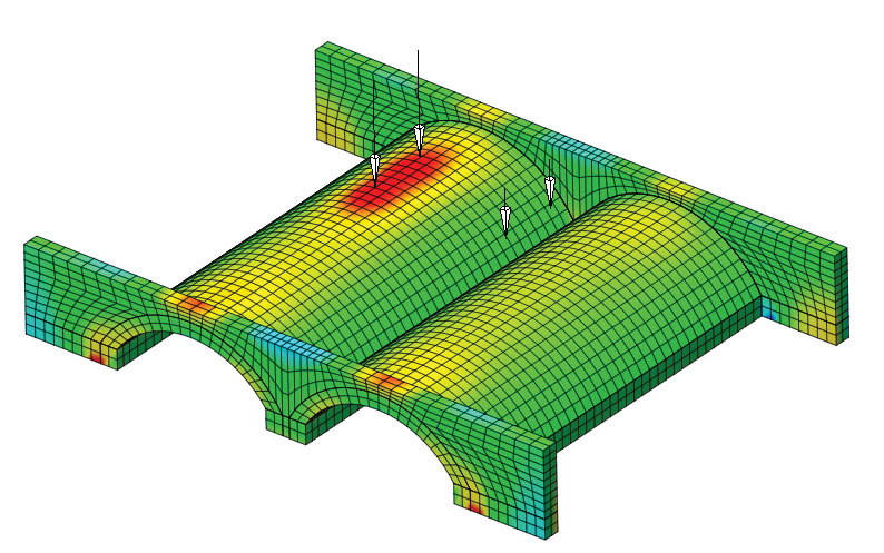
Stress distribution in barrel vaults and spandrel walls.
Repair, Strengthening, and Maintenance
Repairs usually involve localized mortar re-pointing and replacement of deteriorated stone. Often the new stone can be sourced locally, and brought in and shaped as necessary to achieve an appearance matching the original stone. For partial stone replacement, the new stone should be keyed into the existing with bond stone header and/or stainless steel ties. A properly functioning drainage plan is important to mitigate the risk of material deterioration in the arch barrel. Spandrel wall cracks (i.e. separation) can be repaired by installation of tie bars to mechanically connect the wall to the arch barrel. Spandrel walls can also be mechanically connected together with transverse tie bars. Key to the longevity of the bridge is a long-term maintenance program.
The structural capacity of an existing arch bridge can be improved in several ways. A new structural slab can be built immediately under the roadway to spread the vehicular loads to a larger arch section. “Saddling” consists of placing a new, cast-in-place or pre-cast, reinforced concrete arch immediately above the existing arch. In both cases, however, it is difficult to maintain traffic on the bridge during construction, especially on narrow bridges. Cementitious grout can be injected into cracks and voids to restore the structural integrity of the arch barrel. Corrugated steel plates, shotcrete, and FRP can be installed to the intrados, but these approaches may not always be appropriate for historic bridges.
Grouted anchors used to connect a cracked (i.e. separated) spandrel wall to the arch barrel.
Conclusions
Stone masonry arch bridges have successfully served the transportation needs of local communities for more than three centuries, and are now part of the history and heritage of this country. However, many of the existing bridges have exceeded their intended service life and have functional or structural issues, yet remain in service due to their critical location, cost of replacement, community involvement or historic designation. From the structural engineer’s standpoint, understanding the appropriate evaluation methods, analysis techniques, and repair and strengthening options is critical to the preservation and rehabilitation of stone masonry arch bridges.▪