
Gustav Lindenthal’s New York City Hell Gate Bridge ~1917
Captains steering nineteenth century heavy shipping-traffic remained vigilant when navigating the waterway of the 850-foot wide Hell Gate Sector of New York City’s East River, which is flanked by two Manhattan islands and land eastward in Queens, New York. Notoriously ferocious waters, unexpected currents, and huge rocks lurked below the turbulent surface. Yet this economically essential waterway provided major regional freight operations.
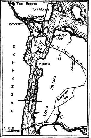
The New York connecting railroad route. Half of the project is viaducts and bridges. Courtesy of Popular Mechanics Magazine, v. XX: 621. 1913.
Prior to the Hell Gate Bridge project, freight trains and trucks, for example from New England, stopped at rail termini, such as at Morris Point in the Bronx, and transferred their shipments onto floating barges bound for a destination terminal, such as in New Jersey, thereby facilitating distribution of goods westward. But the shipping back and forth in the waterways became so congested with ferried traffic that those involved called for modernization.
To expedite a solution to such overcrowding and for safety reasons, citizens pressured Congress to finance a deeper channel-way. Congress, by 1885, allocated approximately $600,000 for the U. S. Army Corps of Engineers to blast 9554 cubic yards of rock out of the Hell Gate channel using 11,808 pounds of nitroglycerine, along with 1218 pounds of “giant powder” (TNT) and 8445 pounds of “black powder” (exploding TNT). Blasting one cubic yard of rock required about nine-tenths of a pound of nitroglycerine – the largest single blast removed 300,000 cubic yards of rock. The Burleigh Drill, diamond drills, and handwork removed more rock. Later, the East River at Hell Gate was dredged from 26 feet of original depth to 40 feet.
As marine traffic flourished, so too did the aggressive pursuit of railroad expansion. Engineers after 1890 knew that the Pennsylvania Railroad was evaluating opportunities for expansion, including construction of a monumental railroad bridge to span the Hell Gate waterway, to connect New England with Long Island through, and into, New York City and westward.
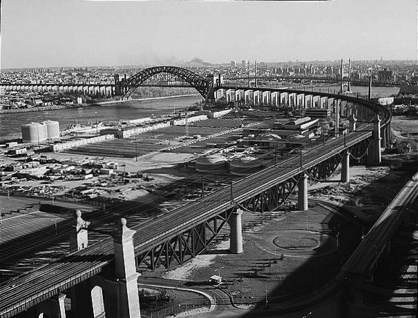
Recent overview of the project looking south, showing the flagship Hell Gate Bridge and the 4-span Little Hell Gate inverted bowstring arches in the foreground. Towers probably by Henry Hornbostel, Architect. Courtesy of www.loc.gov. HAER. NY-121-16. G. Weinstein, Photographer. 1996.
Therefore, the New York Connecting Railroad Company incorporated in 1892, by Oliver Barnes and Alfred Boller, among others. By 1900, a double-track, light Cooper E-40 cantilever bridge design by Boller emerged for the site, but was not accepted.
The existing bridge over the Hell Gate waterway became a reality soon after the turn of the 20th century. In 1900, the Pennsylvania Railroad, together with the New York, New Haven & Hartford Railroad, acquired the 1892 New York Connecting Railroad Charter, with rights to traverse the Hell Gate waterway. To facilitate access to New York Pennsylvania Station, tunnels were in the works as well. After the definite electrification of trains, the Pennsylvania Railroad from 1904-1910 constructed two single-track tunnels under the Hudson River and four tunnels beneath the East River, all traveling through Manhattan’s newly constructed, classical-style 1911 Pennsylvania Station (McKim, Mead and White; demol. 1965.)
The President of the Pennsylvania Railroad selected Lindenthal as “Consulting Engineer and Bridge Architect” of the “East River Bridge Division” of the Hell Gate Bridge project in 1904, at the end of Lindenthal’s term as New York City Bridge Commissioner (1902-4).
In 1905, Lindenthal, after first considering a three-span continuous truss and a three-span cantilever design, presented two steel-arch designs: One a crescent arch, with the top and bottom chord termini converging, and the other a spandrel arch design, with the termini of the top and bottom chords splaying apart. While the Pennsylvania Railroad aspired to a world-class railroad, Lindenthal worked to create an historically noteworthy, substantial and visually unforgettable railroad entrance to New York City. Lindenthal’s natural European attention to quality, long service-life, and aesthetics coincided with contemporary urban movements working to improve the aesthetics of the built environment.
Lindenthal and his 95 assistants, including Othmar Ammann and David Steinman, prepared the designs and specifications for several miles of viaducts running from the Bronx, into Queens, and three bridges; a fixed metal truss bridge over Bronx Kill, the noteworthy Little Hell Gate skew-deck four-span reverse bowstring, and the flagship four-track spandrel-arch bridge over Hell Gate. Construction began with the July, 1912 ground breaking.
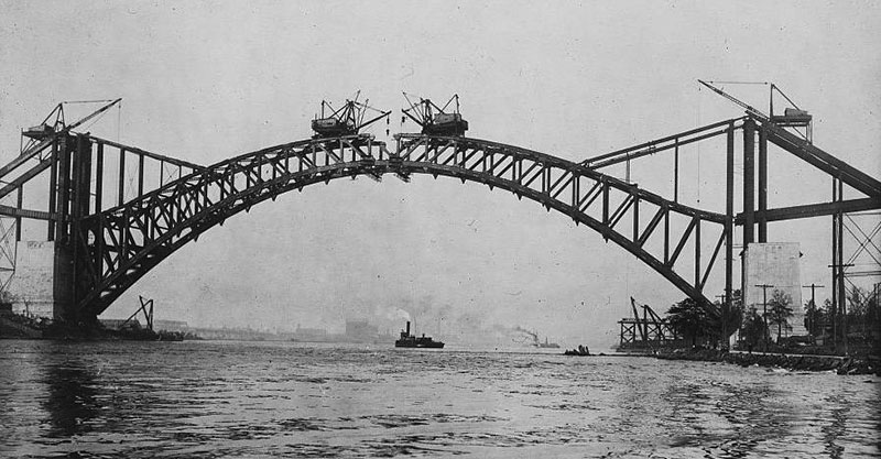
Completing Hell Gate arch top chord over rough waters. structural members manufactured for the floor first act as backstays and counterweights. (Left & Right). The tremendous weights of the towers at the abutments resist the thrust of the bottom chord of the arch where almost all of the forces are transmitted. www.loc.gov HAER 3616-11 Taken 9/30/1915.Accessed Nov. 2012.
The Masonry Footings, Tower Foundations and Towers
The Pennsylvania Railroad’s Joseph N. Crawford, Consulting Engineer, made the initial surveys and wash-borings. Later, core-borings ordered by Lindenthal established the depth to bedrock, confirming on the Wards Island side depths of 55 feet to 140 feet below the mean high water line.
Geological problems on the Wards Island side necessitated difficult, dangerous and complex caisson construction, which was handled by the New York Connecting Railroad’s Chief Engineer, P. G. Brown, Civil Engineer. Here, the tower base and foundation rest on 21 caissons sunk to great depths. Of interest are two rows of deep interlocking reinforced caissons of 30 feet by 125 feet, which act solely to resist the arch thrust and place 20 tons per square foot pressure on the bedrock.
On the Long Island (Queens) side, the excavated tower base, with its foundation weight of eight and one half tons per square foot, is 49 feet thick. It rests on Gneiss bedrock encountered at 15 to 38 feet below the ground surface, and is 104 feet by 140 feet at the base.
Architect Henry Hornbostel designed the 225-foot high portal towers in the project. The Romanesque-Revival towers have ground-level footprints of 103 feet by 139 feet, with the towers then tapering slightly inward up to an entablature, above which an array of simple, well crafted, stepped cornice-moldings support a parapet of repeated small Roman arches. A large Roman arch perforates each of the four tower wall elevations, flanked by two loopholes (medieval vertical slits).
The design concept of the portal towers is a synthesis of historic meaning with new materials and technologies. The towers, appearing to be solid, protective, load-bearing stone castle-keeps, become instead grand-arched open City Gates, built of concrete with vertical and horizontal steel reinforcing rods and granite facings.
The concrete is waterproofed via its careful mix, by smooth-finish toweling before setting, by proper sloping of the concrete for quick water run off, and by the provision of good drain holes. The mortar mix is one part Portland cement, two parts sand, and four parts gravel. There are steel girders in the track floor and roof where the trains pass through the portals.
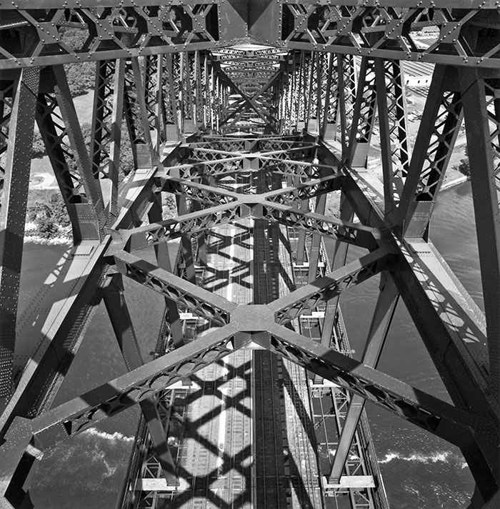
Inside Hell Gate Truss arch, looking down onto the tracks. The truss is 53 feet wide over 4 tracks. Note the lateral bracing and the heaviness of the structural materials. The sidewalks flanking the tracks are capable of supporting an overhead trolley. Courtesy of DaveFrieder.com. All Rights Reserved.
The Steel
The bridge is constructed of 18,900 tons of extra-heavy hard steel. All the rolled steel – and the forged and cast steel pieces after annealing – was tested for bending and tension, multiple times and under various loads. Carbon content in the hard steel measured 0.27 to 0.34 percent. Chemical content was controlled, resulting in maximum sulphur of 0.05 percent, and phosphorus ranging from 0.04 to 0.06 percent. Tests of the hard steel yield point calculated as +/- 38,000 pounds per square inch, and the ultimate tensile strength +/- 71,000 pounds per square inch.
While Lindenthal with certainty used nickel steel alloy for the eye bars and pins in his 1909 cantilevered Queensborough bridge, and considered its use for parts of Hell Gate, he based his decision to not use it on price ($40 more than carbon steel per ton) and on what was thought at the time to be a comparatively insignificant structural advantage. Lindenthal originally specified some structural steel for some parts (floor system and suspenders only) of Hell Gate Bridge but the American Bridge Company provided 100% hard steel for the same price.
In 1910, Lindenthal upgraded the original specifications of the 1904 Pennsylvania Railroad standard live loading of Cooper E-50 to the New York, New Haven and Hartford’s Cooper E-60 loading.
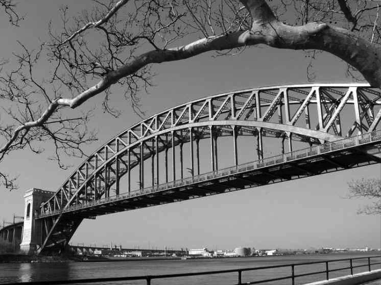
The Hell Gate Bridge today: The truss arch members structure highlighted under sunlight. Courtesy of Adam J. Kirk 2011.
The Hell Gate Arch Superstructure
The two-hinged spandrel arch Hell Gate Bridge, including the towers, is 1017 feet, six inches long (977 feet between towers), 93 feet wide at the floor trusses (60 feet between truss centers), and is comprised of 100% hard steel. The ratio of rise to span is 1: 4.5, with the height of the arch from mean high water at 305 feet. No piers in the water or false work were permitted, so as to not block the river traffic under the bridge’s required 134-foot vertical clearance. It was the most heavily loaded bridge of its day.
The rectangular box-sections are by-and-large of two-inch thick single plates. There are 23 equal sized truss panels, each 42½ feet long. The parabolic bottom chord is a stiffened, double rectangular closed-box, hinged at the abutments where the force equals 28,652 kips or 94.4% of the total force.
Four static conditions for the Hell Gate Bridge’s interesting erection sequence, perhaps best summarized in Ammann’s Transactions of the ASCE paper of 1918 (Parenthetical comment is added):
- Cantilever condition. During erection of first six panels, the truss held at end of top chord by lower backstay.
- Cantilever condition. During erection of remaining panels, truss held at top chord Point 11 by upper backstay.
- Three-hinged arch condition. Back-stays released and trusses connected at bottom chord Point 22 Wards Island side, which acted as hinge, top chord 23-23 (center), and diagonal 23 Wards Island side – 22 Long Island side not connected at 23 Wards Island side. Arch left in this condition until all steelwork had been erected.
- Final or two-hinged condition. All steelwork erected and all members of the center panel fully connected.
The bottom chord arch members were the heaviest to be lifted. The superstructure resists wind pressures of 3100 pounds per linear foot, and lateral forces of 1500 pounds per linear foot, creating 4600 pounds per linear foot of total lateral resistance. The American Railway Engineering Association in 1914 specified total combined lateral and wind force resistances of only 800 pounds per linear foot.
The two ends of the steel arch met in the middle over Hell Gate waterway, aligning exactly, in 1915. During the next year, the viaducts and track floor were under construction.
The Viaduct Spans & Approach Piers
Most of the project rests on elevated viaducts spaced at 90 feet and averaging 100 feet high. Lindenthal originally designed the viaduct piers as steel trestle, so that as the marshy ground below shifted, settled, or was drained for future underground infrastructure, the metal piers and girders assembly could then be adjusted. Authorities noted that since nearby mental and prison inmates housed on the islands could climb metal trestles to escape, Lindenthal in 1914 redesigned the piers as horizontally and vertically reinforced arched concrete supports for the approach viaduct deck plate girder spans. Masonry ordinarily would have been less economical than metal trestle; however, due to high steel prices at the time, concrete became economical.
The American Bridge Company controlled the Wards and Queens plate girder erection. After the arch closed, the Company distributed, on the ground by the viaduct piers, the dismantled backstay structural members and the plate girders which had been used as counterweights during the arch assembly. A locomotive crane on temporary track lifted the members sequentially into place to construct the track floor.
McClintic-Marshall Construction Company handled the Randalls Island and Bronx viaduct sections. Here, girders were riveted and paired up at the shop, and delivered right to the track. A 50-ton steel derrick car or locomotive crane operating on temporary track positioned the girders.
Materials Testing & Construction Observations
Lindenthal was credited by his peers for being the first to use all phases of a bridge under construction for experimental testing. At the time, engineers still worked under theoretical assumptions and individual experience; all advocated acquiring greater scientific knowledge.
To that end, Bauschinger, in Germany, developed a sensitive extensometer (accurate to 1 x 10⁻⁶) with which he tested deformation and elongations of mild steel, and investigated metal fatigue. Lindenthal may have read publications of tests on riveted trusses (Mesnager, 1899) using Rabut’s extensometer, as Lindenthal employed them on parts of New York’s Queensborough Bridge (1909).
Lindenthal resolved to use Hell Gate to share with the profession the findings from this new scientific experimentation. He acquired Howard extensometers and attached them before, during and after construction to all parts of the bridge and equipment.
The extensometers were then monitored. The extensometers attached to the Hell Gate eye bars, for example, revealed uneven stresses during erection. After controlled adjustments, the extensometers reflected a gradual leveling-out of the eye bar stresses to a final, uniform 20,000 pounds per square inch. While measuring the forces on both stays as seven truss panels were placed, the hydraulic jacks put the forward stay in tension and released the lower stay. When too much compression occurred, both stays could be immediately adjusted.
Post Construction
The detailed project records of all forces and tests related in various papers at the time facilitated thorough, subsequent inspections. The original lead paint held up for sixty years. After repainting in 1991, and again in 1996 after Congress allocated $8 million for non-lead paint jobs, Amtrak specified two coats of epoxy primer, a red urethane coat in “Hell Gate Red”, followed by a clear finish coat. The paint faded immediately after both applications. Lawsuits ensued, after which findings were that the paint manufacturer had changed pigment suppliers without ensuring chemical content.
Steinman, in 1918, remarked that the Hell Gate was probably the only bridge-to-date to be scientifically analyzed for bridge stresses. Published studies continued for years after completion, conveying important technical information to other engineers. The superb bridge remains in active service with no major repairs necessary, having outlasted many other railroad bridges. Hell Gate Bridge opened to traffic in March 1917, for a project cost of about $20 million.▪
References
Ammann, Othmar. H. “The Hell Gate Arch Bridge and Approaches of the New York Connecting Railroad over the East River in New York City.”, (with discussion). Transactions of the American Society of Civil Engineers, 1918. 82: 852-1039.
Bairstow, Leonard. “The Elastic Limits of Iron and Steel Under Cyclical Variations of Stress.” Philosophical Transactions of the Royal Society of London. Series A. Containing Papers of a Mathematical or Physical Character. 1911. 210: 35-55.
Black, Archibald. The Story of Bridges. New York: McGraw-Hill. 1936.
Boardman, W. H., ed. “American Railway Association.” (Nov 15 1911 meeting minutes). Railway Age Gazette. July 7 1911. 51: 20: 996.
Forsyth, William. “American Locomotives.” Transactions of the American Society of Civil Engineers. (International Engineering Congress paper). 1905. 54, Part D: 273-311.
Garrison, Ervan. History of Engineering, Technology and Artful Method. Boca Raton (Fla): CRC Press. 1991.
Gruson, L. “Long Unlucky, Rail Bridge Hits $55 Million Repair Jackpot”. The New York Times; Nov 30 1991. 141: Issue 48800: 1.
“Hell Gate.” Scientific American. Sept 20 1873. XXII: 12: 176.
Kilgannon, Corey. “A Bad Impression Outlasts a Bridge’s New Paint.” The New York Times. March 8 2012.
“Is it Safe to Further Increase Wheel Loads of Locomotives?”. Engineering News. Dec. 26 1912. 68: 5: 1219-20.
Jackson, Kenneth T., ed. Encyclopedia of New York City. New Haven: Yale University Press. 1995.
Lanza, Gaetano, et. al. “Discussion on Tests of Steel.” Transactions of the American Society of Civil Engineers. 1904. 54: Part F: 75.
Lindenthal, Gustav. “Bridge Engineering.” Engineering News Record, April 17 1924. 92: Fiftieth Anniversary Number: 652.
Lindenthal, Gustav. “A New Impact Formula.” Engineering News Record, August 1 1912. 68: 5: 216-8.
Lindenthal, Gustav, et. al. “Discussion on Live Loads for Railroad Bridges.” Transactions of the American Society of Civil Engineers. 1905. 54: Part A: 90-1.
Lindenthal, Gustav. “Some Thoughts on Long-Span Bridge Design.” Engineering News Record, 21 Nov 24 1921. 87: 861.
Marsh, Charles F. Reinforced Concrete. New York: Van Nostrand. 1904.
Moreau, Auguste et Georges Petit, eds. Congrès International des Procédés de Construction; Comptes Rendus des Séances et Visites du Congrès (de 1889). Paris: Librairie Polytechnique. 1891.
Petrosky, Henry. Engineers of Dreams; Great Bridge Builders and the Spanning of America. New York: Knopf. 1995.
“The Progress of the Hell Gate Excavations.” Scientific American. Nov 15 1873. XXIX: 20: 304.
Rolwood, Craig J and Robert Drew. Condition Inspection and Analysis of Four, Prominent Railroad Bridges. White Paper. 2007.
Schneider, Charles C. “The Evolution of the Practice of Bridge Building.” Transactions of American Society of Civil Engineers. Paper 993. [June 1905]. 54: 232.
Steinman, D. B. “Stress Measurements on the Hell Gate Arch Bridge.” (With Discussion) Transactions of the American Society of Civil Engineers. [Jan 1918]. 82: 1040-76.
Steinman, D. B. et al. “Secondary Stresses on the Hell Gate Arch Bridge.” (With Discussion) Transactions of the American Society of Civil Engineers. [Jan 1918]. 82: 1077-1124.
“Stress Management.” The Engineer. Aug 8, 1919. No. II: 125-6.
Timoshenko, Stephen P. History of the Strength of Materials. Princeton: Van Nostrand. 1953.
Waddell, J. A. L. Bridge Engineering. New York: John Wiley & Sons. 1 & 2. 1916.
Winsor, H. H., ed. “The Hell Gate Steel Arch Bridge.” Popular Mechanics Magazine. XX: 621. 1913.